


882.01749.00 33 of 93
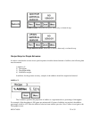
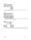
Extrusion - Constant: Wire the “cycle/run” cable (two- conductor gray cable) to a set of
dry (NO VOLTAGE) contacts that CLOSE when the screw rotates. (See Figure 5.) The connection
inside the controller should be on terminal block #10 and PLC input X5.
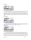
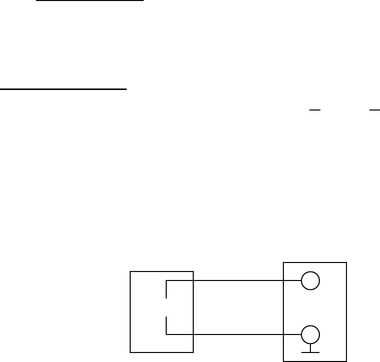
Extrusion - Proportional: Wire the “cycle/run” cable to the extruder signal output that is
proportional to the extruder speed. The signal can be 0-10 VDC or 0-20 mA or 4-20 mA. Jumpers J1
and J2 should be installed for 0-20mA or 4-20mA, and removed for 0-10VDC.
NOTES: 1. Signal voltage from the extruder must to be isolated. Consult factory for
other signal requirements. External signal converter may be required.
2. “Zero” input corresponds to zero screw speed and no additive dosing.
“Maximum” input corresponds to maximum screw speed.
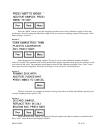
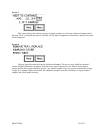
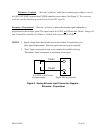
TB #51 _
TB #54 +
0-10 VDC or 0/4-20 mA
Extruder output Digital Dosing controller
Figure 6. Analog Extruder Input Connection Diagram –
Extrusion - Proportional
.