


DFG-SERIES SURFACE GRINDERS OPERATION AND PARTS MANUAL REV #3 (07/13/06) PAGE 16
ASSEMBLY INSTRUCTIONS/OPERATIONS
INSTALLING THE SG24-1000 SAFETY AND DUST
SHIELD ASSEMBLY KIT.
Application: All Models.
Tools Required:
1 each, 5/32 inch Allen wrench.
1 each, 7/16 inch wrench.
2 each, 1/2 inch wrenches.
1 each, flat blade screwdriver.
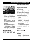
1) If the SURFACE GRINDER is powered by an
engine, disconnect the spark plug wire. If
powered by an electric motor, properly
disconnect the extension cord or SURFACE
GRINDER from the power source.
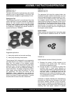
2) Using the allen wrench, remove the bumper
guard P/N 29018-016 from the machine.
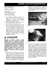
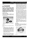
3) Tilt the SURFACE GRINDER back until the
operator handle comes in contact with the
surface. The SURFACE GRINDER may not be
in a stable position in this configuration. To
minimize the possibility of property damage
and/or personnel injury, properly secure an
appropriate weight to the handle for added
stability. Other means can be utilized to support
the frame and provide proper machine stability.
Appropriate wheel chocks are also
recommended. FIGURE 1.
DANGER
EXERCISE EXTREME CAUTION WHEN
WORKING NEAR OR UNDER THE SURFACE
GRINDER WITH THE OPERATOR HANDLE
TILTED BACK IN THE SERVICE POSITION. IF
THE SURFACE GRINDER IS NOT POSITIONED IN
A STABLE CONFIGURATION, WITH ADEQUATE
COUNTERWEIGHT PROPERLY SECURED,
UNEXPECTED MOVEMENT CAN ALLOW THE
SURFACE GRINDER TO FALL BACK TO THE
WORK SURFACE. THE RESULT CAN BE
PROPERTY DAMAGE AND/OR PERSONAL
INJURY.
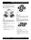
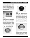
4) Using the 7/16-inch wrench, install the wrap-
around rubber skirt P/N 29018-88 around the
outside perimeter surrounding the multi-
accessory discs. Secure with cap screws P/N
106499-007 and washers P/N 29018-090. The
original bumper and cap screws can also be
utilized as an alternative attachment method.
The notches in the rubbers skirt are provided as
a means to compensate for multi-accessory
attachment wear (if applicable). Adjust the
location of the rubber skirt to provide the
necessary clearance between it and the work
surface. Improper clearance will accelerate skirt
wear. FIGURE 2.
FIGURE 1
FIGURE 2
5) Using the 1/2-inch wrenches, the rectangular
rubber skirt P/N 29018-089 is attached to the
middle support member of the main frame.
Proper installation will have the hose attach
fitting that is riveted to the skirt facing the rear of
the machine. The notches in the rubber skirt are
provided as a means to compensate for multi-
accessory attachment wear (if applicable).
Adjust the location of the rubber skirt to provide
the same clearance as with the wrap-around
rubber skirt P/N 29018-088. The skirt straps PN
29018-092 provide additional support for the
rear skirt assembly. Properly secure with the cap
screws PN 06500-007 and self-locking nuts P/N
08233-005. FIGURE 3.