


DFG-SERIES SURFACE GRINDERS OPERATION AND PARTS MANUAL REV #3 (07/13/06) PAGE 42
MAINTENANCE/SERVICE
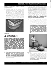
1) Position the SURFACE GRINDER on a suitable
work surface with the V-belts approximately at
waist level.
2) Remove the rubber latches and slide the belt
guard away from the engine/electric motor until it
clears the catch mechanism. Remove the belt
guard from the main frame. Clean the inside of
the belt guard with an appropriate solvent.
Check for signs of wear and damage. Secure in
a proper storage area
.
CAUTION
Observe all applicable safety precautions for the
solvent.
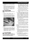
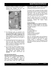
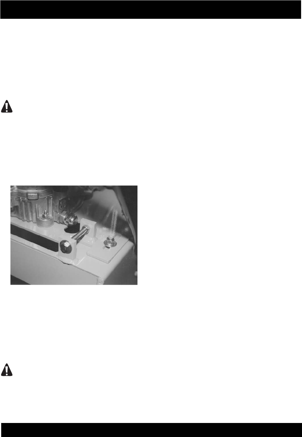
3) Using the 1/2-inch wrenches, loosen the
engine/motor mounting plate cap screws.
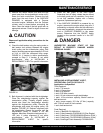
4) With the same wrenches, rotate the engine take-
up cap screws counterclockwise to loosen the V-
belts and allow the engine/electric motor to slide
toward the front of the main frame. FIGURE 43.
FIGURE 43
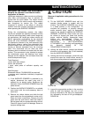
5) Remove the worn V-belts. Inspect the
engine/electric motor and transmission pulleys
for wear and damage. Install the replacement
belts, P/N 29018-012 in pairs. The SURFACE
GRINDER utilizes two V-belts. Always install
replacement belts in matched pairs. Never
replace just one of the V-belts.
CAUTION
Do not operate the SURFACE GRINDER with
only one V-belt installed. One V-belt is not
capable of transmitting proper horsepower and
torque levels to the multi-accessory discs.
a) Do not install replacement belts if the pulleys
have excessively worn grooves. Such
pulleys should be replaced to insure proper
belt fit. Operating the V-belts in worn pulley
grooves will accelerate wear, reduce
horsepower and torque levels and
significantly reduce component service life.
b) A V-belt should never be forced over a
pulley. More belts are broken from this
cause than from actual failure in service.
c) Keep the belts as clean and free of foreign
material as possible. Do not use belt
dressing
6) The centrifugal clutch assembly utilized on both
the gasoline engine powered and Propane
converted SURFACE GRINDERs is designed to
deliver an extended service while requiring
minimal service. However, long term use of the
SURFACE GRINDER can allow the
accumulation of fine dusts and powders within
the clutch assembly. These dusts and powders
can dramatically reduce the capacity of the the
clutch drum bearing, resulting in the following
operational characteristics
:
a) When operating the engine at idle speed,
the centrifugal clutch assembly will not fully
disengage, allowing the multi accessory
discs to rotate at low speed.
b) When the engine is advanced to and/or from
the idle speed position, erratic machine
movement or "grinding" and "thrashing"
noises from the clutch area are detected.
In many cases, clutch assembly removal, a cleaning
of the bearing surfaces and reassembly will solve
the problem.
7) Rotate the take-up cap screws clockwise until
the V-belts have enough tension to not allow
them to fall off the centrifugal clutch and/or
pulleys.
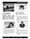
8) Using the 9/16-inch wrench, remove the
retaining cap screw from the engine crankshaft.
Using the 5/32 inch allen wrench, loosen the two
set screws located near the snap ring. The
clutch can now be removed from the engine
crankshaft. FIGURE 44.
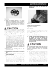
9) The centrifugal clutch is comprised of a
rotor/shoe assembly, a drum/pulley assembly, a
thrust washer and retaining snap ring.
a) Using the snap ring pliers, remove the snap
ring from the clutch assembly. FIGURE 45.