


DFG-SERIES SURFACE GRINDERS OPERATION AND PARTS MANUAL REV #3 (07/13/06) PAGE 41
MAINTENANCE/SERVICE
3) Remove the rubber latches and slide the belt
guard away from the engine/electric motor until it
clears the catch mechanism. Remove the belt
guard from the main frame. If the SURFACE
GRINDER is equipped with a Propane
converted engine, determine that the Propane
cylinder valve is closed before uncoupling the
hose. Clean the inside of the belt guard with an
appropriate solvent. Check for signs of wear and
damage.
CAUTION
Observe all applicable safety precautions for the
solvent.
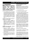
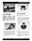
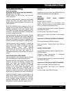
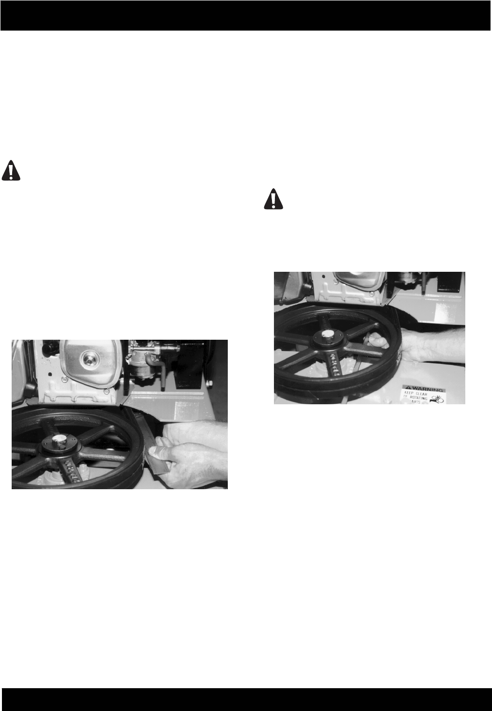
4) Check the belt tension using the spring scale or
belt tension tool midway between the engine
clutch pulley and the transmission pulley. Belt
tension should measure approximately 0.22 inch
at 3-1/4 to 4-3/8 lbs. measured force range.
FIGURE 41. If tension is within specifications,
proceed to Step 5. If tension is not within
specifications, refer to INSTALLING A
REPLACEMENT V-BELT for specific information
FIGURE 41
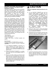
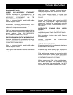
5) Belt alignment is checked with the straightedge.
Place the straightedge squarely against the
transmission pulley. Properly aligned pulleys
should also place the straightedge squarely
against the engine/motor pulley. Remove the
straightedge and rotate the engine pulley 120
degrees. FIGURE 42. Recheck alignment with
the straightedge. Repeat the process until the
engine/motor pulley is rotated a full 360
degrees. Maximum allowable misalignment is + -
1/32 inch. If pulley alignment is not within
specifications, refer to INSTALLING A
REPLACEMENT V-BELT for specific
information.
6) Install the belt guard to the main frame.
Determine that all safety related decals affixed
to the belt guard are fully readable. If any decal
is not fully readable, replace with a factory
approved, replacement part only.
7) If the SURFACE GRINDER is powered by an
engine, reconnect the engine spark plug wire. If
powered by an electric motor and the machine is
to be used immediately, reconnect the extension
cord or SURFACE GRINDER to the power
source. Determine that the ON/OFF switch
located on the operator handle is in the OFF
position
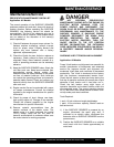
DANGER
UNEXPECTED MACHINE START UP CAN
RESULT IN PROPERTY DAMAGE AND/OR
PERSONAL INJURY.
FIGURE 42
INSTALLING A REPLACEMENT V-BELT,
CENTRIFUGAL CLUTCH OR PULLEY.
Application: As Specified.
Tools Required:
1 each, 7/16 wrench.
2 each, 1/2 wrenches.
1 each, 9/16 wrench.
1 each, 5/32 Allen wrench.
1 each, 16 inch minimum length straightedge.
1 each, 10 lbs minimum capacity, tension scale or
belt tension tool.
1 each, torque wrench, 35 ft lbs (47 Nm.) capacity
with 7/16 inch and 9/16 inch sockets.
1 each, belt tension tool.
Parts Required:
2 each, V-Belt,B50 P/N 29018-014
1 each, Pulley Assembly P/N 29018-012 (Gas Engine)
1 each, Pulley Assy. P/N SFSG240500 (Electric, 60 Hz.)
1 each, Pulley Assy. P/N SFSG240510 (Electric, 50 Hz)
1 each, Centrifugal Clutch Assembly P/N 29018-022.