


DFG-SERIES SURFACE GRINDERS OPERATION AND PARTS MANUAL REV #3 (07/13/06) PAGE 30
ASSEMBLY INSTRUCTIONS/OPERATIONS
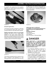
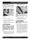
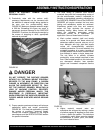
ADJUSTING THE OPERATOR HANDLE HEIGHT.
Application: All Models.
The DFG Series SURFACE GRINDER incorporates
a handle that can be adjusted to compensate for
variances in operator heights. Three adjustment
heights are provided. Correct handle height can
increase overall machine productivity and reduce
operator fatigue.
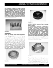
FIGURE 29
Tools Required:
1 each, 3/4 wrench or suitable alternative.
1) Using the wrench, loosen the 1/2-inch hexagon
nuts from the stud assemblies that retain the
handle to the main frame.
2) Using the wrench, remove the 1/2-inch cap
screws that retain the handle in position on the
main frame.
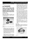
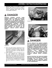
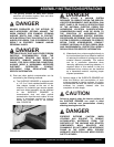
DANGER
EXERCISE EXTREME CAUTION WHEN
REMOVING THE RETAINING CAPSCREWS
FROM THE MAIN FRAME. WHEN THE FINAL
CAPSCREW IS REMOVED, THE HANDLE IS
PROVIDED WITH NO EXTERNAL SUPPORT AND
WILL IMMEDIATELY DROP TO THE FLOOR.
SUCH OCCURRENCE CAN RESULT IN
PROPERTY DAMAGE AND/OR PERSONAL
INJURY.
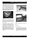
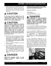
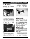
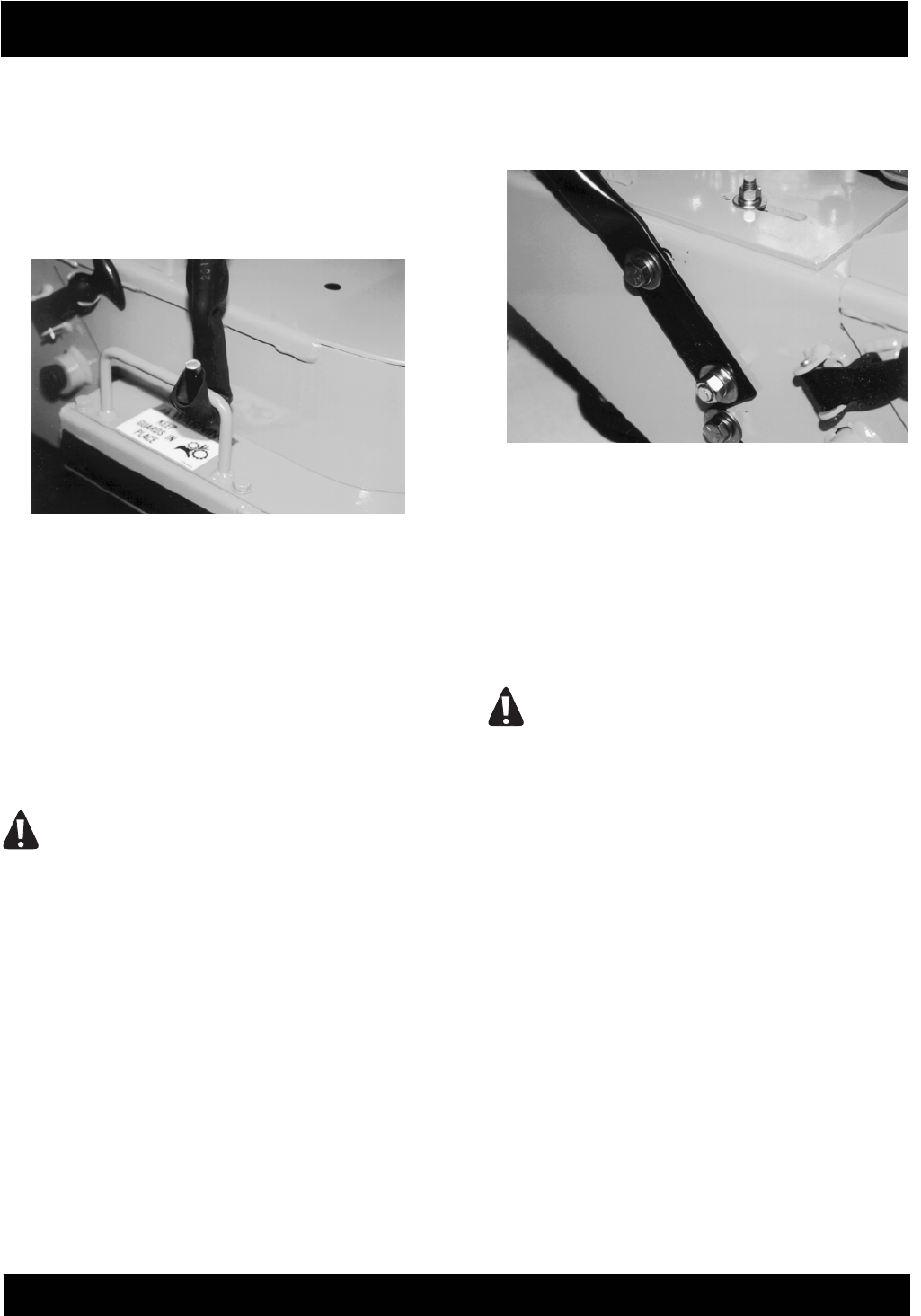
3) Reposition the operator handle in the desired
location that aligns the hole in the handle with
the threaded hole in the main frame. Replace
the 1/2-inch hexagon cap screws and properly
tighten with the wrench. FIGURE 30.
4) Using the wrench, properly tighten the 1/2-inch
hexagon nuts on the stud assemblies that retain
the handle to the main frame.
FIGURE 30
STARTING THE DFG/E SERIES ELECTRICALLY
POWERED SURFACE GRINDER ON THE
JOBSITE.
1) Position the SURFACE GRINDER on a flat and
level surface of firm foundation.
2) Determine that the ON/OFF switch located on
the operator handle is in the OFF position.
DANGER
UNEXPECTED MACHINE START UP CAN
RESULT IN PROPERTY DAMAGE AND/OR
PERSONAL INJURY.
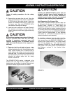
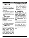
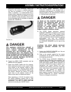
3) Select the appropriate operating voltage for the
electric motor. The motor is designed to operate
from a clean, 20 ampere, 115 VAC, 60 Hz
nominal or a clean, 10 ampere, 230 VAC, 60 Hz
nominal power source. A clean power source
refers to the amperage available on the
individual electrical circuit selected. Additional
electrical products already utilizing the same
circuit will reduce the available amperage,
resulting in starting and operational difficulties.
A voltage switch (115/230 VAC, 60 Hz) is
provided on the motor. For added security, the
voltage switch can be locked in position with a
combination or keyed lock with an extended
shank length. FIGURE 31.