


DFG-SERIES SURFACE GRINDERS OPERATION AND PARTS MANUAL REV #3 (07/13/06) PAGE 25
ASSEMBLY INSTRUCTIONS/OPERATIONS
CAUTION
Follow all safety precautions for the safety
solvent.
2) Remove the cap screw from the unit. Clean the
newly exposed areas of the insert and SCRAPE-
R-TACH unit with the safety solvent. Clean and
inspect the threaded holes found in older units
for excess wear. New style SCRAPE-R-TACH
units feature a through hole design.
3) Index the insert to expose a new edge. Reinstall
the capscrew and apply a torque value that
properly seats the insert firmly against the body
of the unit.
CAUTION
An insufficient seating torque value will allow the
insert to become loose from the unit body,
resulting in premature component wear and
improper scraping action. An excessive torque
value will strip the threads of the capscrew or
unit body.
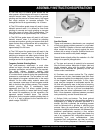
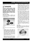
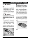
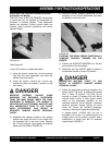
4) Determine that the unit body is free to rotate
about the 5/16 inch diameter capscrew that
retains the body to the unit. A body that does not
freely rotate indicates that a material build-up
exists between the rubber mount and retaining
capscrew exits. This build-up must be removed
by disassembling the body from the unit and
cleaning all contact areas with the safety
solvent. FIGURE 20.
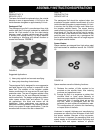
The SCRAPE-R-TACH system is designed to be
installed with the edge of the tungsten carbide
inserts facing the direction of rotation. Markings are
provided to indicate proper direction of rotation.
FIGURE 20
CAUTION
Installing the SCRAPE-R-TACH system with the
tungsten carbide inserts facing opposite the
rotation direction will not deliver satisfactory
material removal rates and result in premature
component wear requiring early replacement.
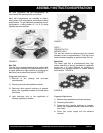
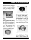
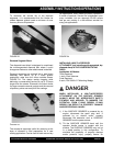
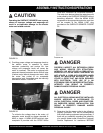
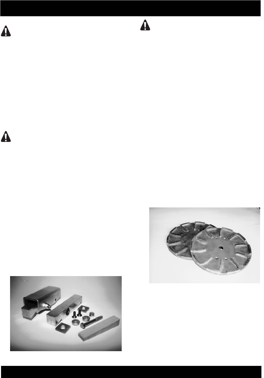
Multi-Segmented, Dry Diamond Disc
Many times increased concrete removal rates can
be achieved with the use of multi-segmented, dry
diamond discs. FIGURE 21. These discs are
designed to operate dry or can also be utilized with
water. If the wet option is chosen, an external source
for providing water must be devised. No provision for
water use is provided with the SURFACE GRINDER.
Typical discs are approximately 10 inch diameter
and feature up to 20 diamond segments that are
welded or brazed to each assembly.
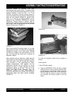
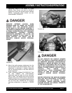
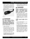
To install the multi-segmented, dry diamond discs,
the standard, aluminum, multi-accessory discs are
first removed from the SURFACE GRINDER. The
diamond discs fasten directly to the gimbal heads
with 3/8 inch diameter x 1 inch long Allen head
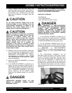
capscrews. FIGURE 22. The rear wheel assembly is
then placed in the lowest position to compensate for
the thickness variance of the diamond discs.
FIGURE 23.
FIGURE 21