


DFG-SERIES SURFACE GRINDERS OPERATION AND PARTS MANUAL REV #3 (07/13/06) PAGE 44
MAINTENANCE/SERVICE
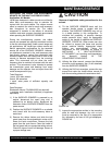
REPLACING THE LORD® TYPE ELASTOMERIC
MOUNTS ON THE MULTI-ACCESSORY DISCS.
Application: All Models.
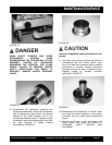
Lord® type elastomeric rubber mounts are utilized to
allow each multi-accessory disc to maintain full
contact with the work surface. The rubber mounts
afford a constant flex rate for each multi-accessory
disc throughout its service life. The rubber
compound is resistive to the effects of ultraviolet
radiation and most common chemicals encountered
when operating the SURFACE GRINDER .
During the manufacturing process, the rubber
mounts are pressed into specially machined cavities
in the disc mounting plates. Under normal usage and
job applications, the Lord® type rubber mounts will
deliver appropriate performance for the expected
service life of the SURFACE GRINDER. However,
an attachment mounted in the multi-accessory disc
that directly strikes a vertical floor obstruction with
sufficient impact force can cause one or more of the
mounts to become separated from the mounting
plate. This occurrence will not allow the multi-
accessory disc to maintain full contact with the work
surface. This occurrence is also intended to protect
the transmission gears and bearings from costly
damage and the operator from an impact force that
could cause personal injury.
Tools Required:
1 each, 5/16 allen wrench.
2 each, 5/8 wrenches.
1 each, arbor press of sufficient capacity and
stability.
Parts Required:
Elastomeric Mount, P/N 29018-055 (as required).
1 container each: Installation Lubricant (or approved
equivalent).
1) If the SURFACE GRINDER is powered by an
engine, disconnect the spark plug wire. If
powered by an electric motor, disconnect the
extension cord or SURFACE GRINDER from the
power source.
2) Position the SURFACE GRINDER on a suitable
work bench with the multi-accessory discs at
waist level
3) Remove the rubber latches and slide the belt
guard away from the engine/electric motor until it
clears the catch mechanism. Remove the belt
guard from the main frame. Clean the inside of
the belt guard with an appropriate safety solvent.
Check for signs of wear and damage. Secure in
a proper storage area.
CAUTION
Observe all applicable safety precautions for the
solvent.
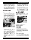
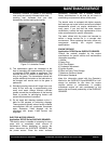
4) Tilt the SURFACE GRINDER back until the
operator handle comes in contact with the
surface. The SURFACE GRINDER may not be
in a stable position in this configuration. To
minimize the possibility of property damage
and/or personal injury, apply an appropriate
weight to the handle to stabilize the SURFACE
GRINDER. FIGURE 48. Other means can also
be utilized to support the frame and provide
proper machine stability. Appropriate wheel
chocks are recommended.
Follow the
instructions for this procedure as outline in
INSTALLING A MULTI-ACCESSORY
ATTACHMENT (not including multi-segmented,
dry diamond blades) IN THE
COUNTERROTATING DISCS.
5) Utilizing the Allen wrench, remove the affected
aluminum multi-accessory disc (if still attached)
from the SURFACE GRINDER.
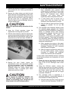
6) Utilizing the 9/16-inch wrenches, remove the cap
screws that retain the Lord® rubber mounts to
both the mounting plate and transmission shaft.
FIGURE 48
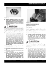
7) Inspect the appropriate cavities in the mounting
plate for wear and damage. Any nick or burr
must be removed by the use of an appropriate
file, followed by the use of 240 grit sandpaper.
FIGURE 49.