


DFG-SERIES SURFACE GRINDERS OPERATION AND PARTS MANUAL REV #3 (07/13/06) PAGE 37
ASSEMBLY INSTRUCTIONS/OPERATIONS
intentionally sloped for drainage considerations.
Very few, if any, floors are specifically designed to
be unflat. Unfortunately, many turn out that way.
Flatness and levelness are both desirable, but have
different implications for the floor user. Flatness is
critical where the user's main concern is the
behavior of wheeled type vehicles. Levelness is
critical where the user's main concern is with fixed
structures such as shelving, racks and the
placement of machine tools.
Exceptions exist, but for most users, flatness is more
important than levelness. The reasoning is that fixed
equipment can be shimmed or adjusted to
compensate. However, it is not as easy to adapt a
wheeled vehicle to a floor that is not flat enough to
allow for proper action.
Flatness and levelness also have different
implications for the floor contractor. Flatness is
determined mainly by finishing methods. Levelness
is determined mainly by the side forms.
Defined Versus Random Traffic Patterns
Floors are subject to two kinds of traffic patterns:
defined and random. On a defined traffic floor,
vehicle movement is confined to fixed paths. On a
random traffic floor, vehicles are free to roam,
though inevitably, some traffic patterns are used
more than others.
The distinction is important because the two kinds of
traffic demand different methods of measuring
surface regularity. On a defined traffic floor, a
continuous (or nearly continuous) profile in each of
the paths can be measured. But where traffic is
random, the possible travel paths are infinite in
number. What usually results is statistical sampling;
selected points or lines are checked and assumed
that they represent the whole floor surface.
The highest degree of surface regularity is found
among the defined traffic floors. Defined traffic floors
allow the designer and contractor to focus on a
limited number of critical areas. When a defined
traffic floors is out of tolerance, it is relatively easy to
identify the defects for correction---usually by
employing a grinding process.
How to Define Surface Regularity
Since the middle 1980s, new methods of defining
surface regularity have been adopted as national
standards. Older methods will continue to be utilized,
although they are less effective. The following
methods will be discussed:
1) The F number system for random traffic floors
2) The TR 34 system for defined traffic floors
Both methods are not of equal value. For random
traffic floors, F numbers provide the most complete
and consistent system. For defined traffic floors, the
TR34 system is superior.
The F number system utilizes a pair of numbers to
define surface regularity. The flatness number, Ff, is
based upon the curvature over a horizontal distance
of 24 inches. The levelness number, Fl, is based
upon the floor slope over a horizontal distance of 10
feet. The standard test for F numbers is specified in
ASTM E1155 and/or most recent version.
With both Ff and Fl, higher numbers mean greater
surface regularity. Though the scale ranges from
zero to infinity, almost all floors have F numbers
between 10 and 100 for both flatness and levelness.
Since the scale is linear, an Ff50 floor is exactly
twice as flat as an Ff25 floor.
Most F number specifications are written in a two tier
format. The overall F numbers apply to the floor
taken as a whole. The local F numbers apply to each
individual slab and are usually only one half to two
thirds the overall values.
The overall F numbers are not just simple averages.
ASTM E1155 covers how to combine F numbers.
The two tier format encourages contractors to
achieve good surface regularity while allowing for
minor defects. The attempt is to pour the entire floor
to the specified overall F numbers. If, for instance,
the construction crew has a bad day and fails to
meet the specified overall numbers for the slab, the
slab can still be accepted provided it meets the
specified local numbers.
Such an occurrence serves as a warning to the crew
that it must strive for a better performance on later
slabs, so as to bring the overall F numbers up to the
specified values. If a slab fails to meet even the
specified local numbers, it must be repaired or
replaced, but such failures seldom occur if all parties
understand what is expected from the start.
Designers are not obligated to use this two tier
format. Some designers specify a single F number
pair (Ff and Fl) which applies to each individual slab.
But this also raises the risk that slabs will be
rejected.
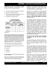
FIGURE 40 depicts the overall and minimum F
numbers for various floor classes. The floor