


Chapter 5: Advanced Serverboard Setup
5-5
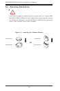
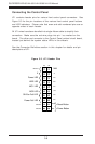
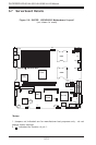
5-3 Connecting Cables
Now that the processors are installed, the next step is to connect the
cables to the serverboard. These include the data (ribbon) cables for the
peripherals and control panel and the power cables.
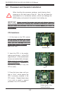
Connecting Data Cables
The ribbon cables used to transfer data from the peripheral devices have
been carefully routed in preconfigured systems to prevent them from block-
ing the flow of cooling air that moves through the system from front to back.
If you need to disconnect any of these cables, you should take care to keep
them routed as they were originally after reconnecting them (make sure the
red wires connect to the pin 1 locations). If you are configuring the sys-
tem, keep the airflow in mind when routing the cables. The following data
cables (with their serverboard connector locations noted) should be connected.
See the serverboard layout figure in this chapter for connector locations.
z CD-ROM drive cable (J6)
z SCSI drive cable (JA1)
z Control Panel cable (JF1, see next page)
z Floppy drive cable (J12)
z Front Side USB cable (JD2)
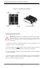
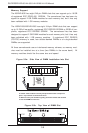
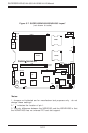
Connecting Power Cables
The X6DHR-8G/X6DHR-8G2/X6DHR-X8G has a 20-pin primary power supply
connector at J1B1 designated "ATX Power" for connection to the ATX
power supply. Connect the appropriate connector from the power supply
to the J1B1 connector to supply power to the serverboard. The 12V 8-pin
processor power connector at J1D1 and the 12V 4-pin power connector at
J38 must also both be connected to your power supply. See the Connector
Definitions section in this chapter for power connector pin definitions.