


5-16
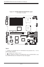
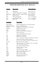
SUPERSERVER 6014H-8/6014H-82/6014H-X8 Manual
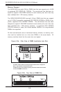
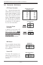
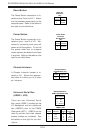
Power Button
The Power Button connection is lo-
cated on pins 1 and 2 of JF1. Mo-
mentarily contacting both pins will
power on/off the system. To turn off
the power when set to suspend
mode, depress the button for at least
4 seconds. Refer to the table on the
right for pin definitions.
Pin
Number
1
2
Definition
PW_ON
Ground
Power Button
Connector
Pin Definitions
(JF1)
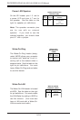
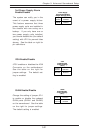
Universal Serial Bus
(USB0/1, JD2)
There are two Universal Serial
Bus ports (USB0/1) located on the
I/O backpanel and an additional
two (USB2/3) next to the CMOS
Clear pads (JBT1). USB2/3 can be
used to provide front side chassis
access (cables not included). See
the tables on the right for pin defi-
nitions.
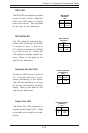
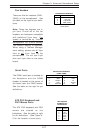
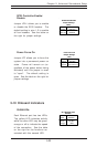
Chassis Intrusion
A Chassis Intrusion header is lo-
cated at JL1. Attach the appropri-
ate cable to inform you of a chas-
sis intrusion.
Pin
Number
1
2
Definition
Intrusion Input
Ground
Chassis Intrusion
Pin Definitions (JL1)
Pin# Definition
1 +5V
2 P0-
3 P0+
4 Ground
Pin
Number
2
4
6
8
10
Definition
+5V
PO-
PO+
Ground
Ground
Pin
Number
1
3
5
7
Definition
+5V
PO-
PO+
Ground
USB Pin Definitions
USB2/3 (JD2)
USB0/1 (Backpanel USB)
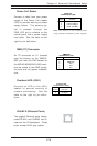
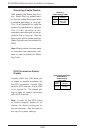
Reset Button
The Reset Button connection is lo-
cated on pins 3 and 4 of JF1. Attach
it to the hardware reset switch on the
computer case. Refer to the table on
the right for pin definitions.
Pin
Number
3
4
Definition
Reset
Ground
Reset Pin
Definitions
(JF1)