


5-14
SUPERSERVER 6014H-8/6014H-82/6014H-X8 Manual
5-8 Connector Definitions
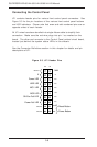
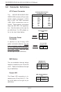
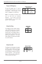
Power LED
The Power LED connection is lo-
cated on pins 15 and 16 of JF1. Re-
fer to the table on the right for pin
definitions.
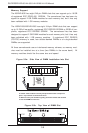
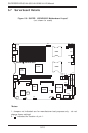
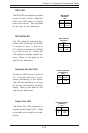
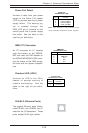
ATX Power Connector
The X6DHR-8G/X6DHR-8G2/
X6DHR-X8G includes a 20-pin main
power supply connector (J1B1)
and a 4-pin 12V PWR connector
(J38). Both connections are re-
quired. These power connectors
meet the SSI EPS 12V specifica-
tion. See the table on the right for
pin definitions. For J38, please re-
fer to the item listed below.
Pin
Number
15
16
Definition
Vcc
Control
PWR_LED Pin Definitions
(JF1)
Pins #
1 & 2
3 & 4
Definition
Ground
+12 V
+12V 4-pin Connector
(J38)
Required
Connection
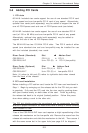
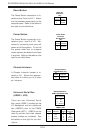
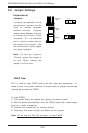
Processor Power
Connector
In addition to the Primary ATX
power connector (above), the 12v
8-pin processor power connector
at J1D1 must also be connected to
your power supply. See the table
on the right for pin definitions.
Pins
1 thru 4
5 thru 8
Definition
Ground
+12v
CPU 8-pin PWR
Connector (J1D1)
Required
Connection
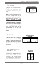
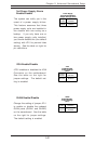
NMI Button
The non-maskable interrupt button
header is located on pins 19 and 20
of JF1. Refer to the table on the right
for pin definitions.
Pin
Number
19
20
Definition
Control
Ground
NMI Button Pin
Definitions (JF1)
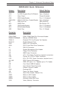
Pin # Definition
11 +3.3V
12 -12V
13 COM
14 PS_ON
15 COM
16 COM
17 COM
18 -5V
19 +5V
20 +5V
Pin # Definition
1 +3.3V
2 +3.3V
3COM
4+5V
5COM
6+5V
7COM
8PW-OK
9 5VSB
10 +12V
ATX 20-pin Power Connector
Pin Definitions (J1B1)