


5-24
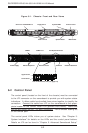
SUPERSERVER 6014H-8/6014H-82/6014H-X8 Manual
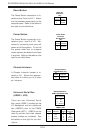
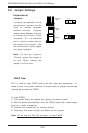
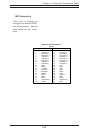
Pin Number Function
1 GND
3 GND
5 Key
7 GND
9 GND
11 GND
13 GND
15 GND
17 GND
19 GND
21 GND
23 GND
25 GND
27 GND
29 GND
31 GND
33 GND
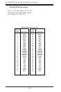
Pin Number Function
2 FDHDIN
4 Reserved
6 FDEDIN
8 Index-
10 Motor Enable
12 Drive Select B-
14 Drive Select A-
16 Motor Enable
18 DIR-
20 STEP-
22 Write Data-
24 Write Gate-
26 Track 00-
28 Write Protect-
30 Read Data-
32 Side 1 Select-
34 Diskette
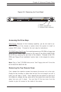
Floppy Connector Pin Definitions (J12)
Floppy Connector
The floppy connector is located
on J12. See the table below for
pin definitions.
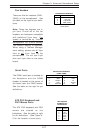
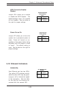
5-11 Floppy, Hard and SCSI Disk Drive Connections
Note the following when connecting the floppy and hard disk drive cables:
• The floppy disk drive cable has seven twisted wires.
• A red mark on a wire typically designates the location of pin 1.
• A single floppy disk drive ribbon cable has 34 wires and two connectors
to provide for two floppy disk drives. The connector with twisted wires
always connects to drive A, and the connector that does not have
twisted wires always connects to drive B.