


5-18
SUPERSERVER 6014H-8/6014H-82/6014H-X8 Manual
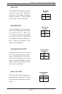
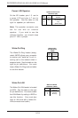
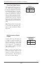
Power LED/Speaker
On the JD1 header, pins 1-3 are for
a power LED and pins 4-7 are for
the speaker. See the table on the
right for speaker pin definitions.
Note: The speaker connector pins
are for use with an external
speaker. If you wish to use the
onboard speaker, you should close
pins 6-7 with a jumper.
Speaker Connector Pin
Definitions (JD1)
Pin
Number
4
5
6
7
Function
+
Key
Definition
Red wire, Speaker data
No connection
Key
Speaker data
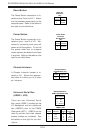
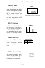
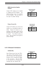
Wake-On-Ring
The Wake-On-Ring header (desig-
nated JWOR) allows your computer
to receive and "wake-up" by an in-
coming call to the modem when in
suspend state. See the table on the
right for pin definitions. You must
have a Wake-On-Ring card and cable
to use this feature.
Wake-on-Ring
Pin Definitions
(JWOR)
Pin
Number
1
2
Definition
Ground
Wake-up
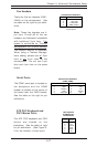
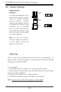
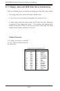
Wake-On-LAN
The Wake-On-LAN header is located
at JWOL. See the table on the right
for pin definitions. You must enable
the LAN Wake-Up setting in BIOS to
use this function. (You must also
have a LAN card with a Wake-On-
LAN connector and cable.)
Pin
Number
1
2
3
Definition
+5V Standby
Ground
Wake-up
Wake-On-LAN Pin
Definitions (JWOL)