


Chapter 5: Advanced Serverboard Setup
5-9
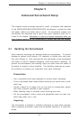
5-6 Adding PCI Cards
1. PCI slots
6014H-8: Included riser cards support the use of one standard PCI-X card
of any speed and one low-profile PCI-X card of any speed. Alternatively,
optional riser cards (sold separately) may be added to support the use of
one x8 PCI-Express card and one x4 PCI-Express card (see below).
6014H-82: Included riser cards support the use of one standard PCI-X
card (of 100 or 66 MHz) and one low-profile PCI-X card of any speed.
Alternatively, optional riser cards (sold separately) may be added to
support the use of two x8 PCI-Express cards.
The 6014H-X8 has two 133 MHz PCI-X slots. Two PCI-X cards of either
speed (one standard size and one low-profile) may be installed for use
with the included (standard) riser cards.
Riser Cards (Standard) Slot
Add-on Card
CSE-RR1U-X PCI-X (L) PCI-X
CSE-RR1U-XLP Univ. PCI (R) PCI-X (low profile)
Riser Cards (Optional) Slot
Add-on Card
CSE-RR1U-EL Univ. PCI (L) PCI-E
CSE-RR1U-ELP* Univ. PCI (R) Low-profile PCI-E
Note: (L) refers to left and (R) refers to right-side slots when viewed
from the front of the chassis.
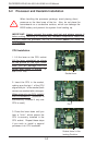
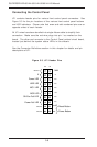
2. PCI card installation
Before installing a PCI add-on card, locate the PCI riser card mentioned in
Step 1. Begin by swinging out the release tab for the PCI slot you wish
to populate. Fully seat the PCI card into the riser card by pushing down
with your thumbs evenly on both sides of the card. Finish by pushing
the release tab back to its original (locked) position. Follow this proce-
dure when adding a card to the other slot.
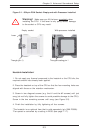
The PCI slot shields protect the serverboard and its components from EMI
and aid in proper ventilation, so make sure there is always a shield covering
each unused PCI slot.
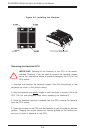
*Use of the CSE-RR1U-ELP riser card requires a slight repositioning of the
release tab mechanism on the low-profile slot: Remove the screw from the
release tab mechanism and slide the mechanism to the left. Then secure it
with the same screw but in the upper hole (see page 6-2 for diagram).