


Chapter 5: Advanced Serverboard Setup
5-19
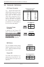
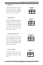
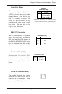
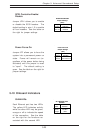
Power Fail Detect
Connect a cable from your power
supply to the Power Fail header
(JP9) to provide warning of power
supply failure. This warning sig-
nal is passed through the
PWR_LED pin to indicate on the
control panel that a power supply
has failed. See the table on the
right for pin definitions.
Power Fail
Pin Definitions (JP9)
Pin
Number
1
2
3
4
Definition
P/S 1 Fail Signal
P/S 2 Fail Signal
P/S 3 Fail Signal
Reset (from MB)
Note: This feature is only available when
using redundant Supermicro power supplies.
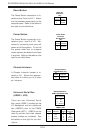
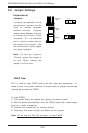
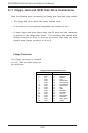
SMB (I
2
C) Connector
An I
2
C connector at J11 (located
near the battery on the X6DHR-
8G2 and near the IPMI header on
the X6DHR-8G/X6DHR-X8G) moni-
tors the status of the PWR supply,
the fans and the system tempera-
ture.
SMB PWR
Pin Definitions (J27)
Pin #
1
2
3
4
5
Definition
Clock
SMB Data
N/A
N/A
N/A
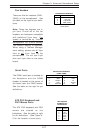
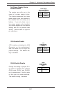
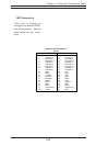
Overheat LED (JOH1)
Connect an LED to the JOH1
header to provide warning of
chassis overheating. See the
table on the right for pin defini-
tions.
Pin
Number
1
2
Definition
+5V
OH Active
Overheat LED
Pin Definitions (JOH1)
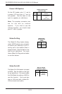
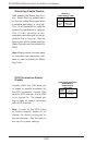
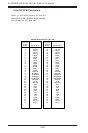
GLAN1/2 (Ethernet Ports)
Two gigabit Ethernet ports (desig-
nated GLAN1 and GLAN2) are lo-
cated on the I/O backplane. These
ports accept RJ45 type cables.