


1. Product Description DIP Switch Functions
10
PDRP-1001 Instruction Manual PN 50734:D0 04/06/01
DIP Switch Functions
The table below describes the DIP switch functions. For a more detailed explaination see "Setting Mode
of Operation" on page 28.
Options
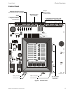
Three optional modules are available for use on the control panel. The control panel provides mounting
slots for two of these optional module boards.
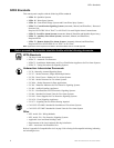
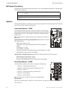
Transmitter Module - 4XTM
The Transmitter Module provides a supervised output for a Local Energy
Municipal Box transmitter and alarm and trouble reverse polarity circuits for
Remote Station Service. Also included is a DISABLE switch and disable
trouble LED.
Note: As a jumper option, the alarm reverse polarity circuit will open on trouble if no
alarm exists.
Specifications for Local Energy Municipal Box service (NFPA 72 Auxiliary
Fire Alarm System)
Supervisory current: 5.0 mA.
Trip current: 0.35 amps (subtracted from Notification Appliance
power).
Coil Voltage: 3.65 VDC.
Coil resistance: 14.6 ohms.
Maximum allowable wire resistance between panel and trip coil: 3 ohms.
Municipal Box wiring can leave the building.
Specifications for Remote Station Service (NFPA 72 Remote Station Fire Alarm System)
Maximum load for each circuit: 10 mA.
Reverse polarity output voltage: 24 VDC.
Remote Alarm and Remote Trouble wiring can leave the building.
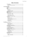
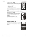
Zone Relay Module - 4XZM
The Zone Relay module provides Form-C contacts for the following:
• Relay #1 - Alarm/Alarm Pressure NAC
• Relay #2 - Alarm Pressure/Auxiliary Supervisory NAC
• Relay #3 - Release 1
• Relay #4 - Auxiliary Supervisory NAC/Release 2
• Relay #5 - System Alarm
• Relay #6 - System Trouble
Note: As a jumper option, the first four relays can be made silenceable.
Specifications
Dry Form-C contacts rated: 2.0 amps @ 30 VDC (resistive), 0.5 amps @ 30
VAC (resistive).
#1 & #2 Mode of
Operation
Determines how NACs and Releasing Circuits respond to an alarm.
#3, #4 & #5 Timer Selects Discharge Timer setting.
Note: See “Setting Mode of Operation” on page 28 for a more detailed explanation of DIP switch
functions.
TB1
TBL
J1
J2
4XTMF.cdr
TB1
LATCH
DISABLE
J2
4XZMF.cdr