


Appendix D: Testing & Maintenance Troubleshooting
52
PDRP-1001 Instruction Manual PN 50734:D0 04/06/01
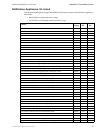
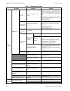
Table 9 Troubleshooting Table
Symptom Problem Solution
AC
Power
LED ON
System trouble
LED ON
Circuit trouble
LED ON
Notification appliance circuit
trouble
1. Check TB2 for proper connections.
2. Remove all field wiring and install dummy ELR at
output circuit. Check for supervisory voltage across it,
(Normal -2.3 V), if problem persists, replace circuit
board.
3. Removed dummy ELR, reconnect field wiring and
measure voltage across output; (trouble-5V, short 0V).
4. Check for ELR at last device.
5. Check field wiring.
Any of the right
column yellow
LEDs flashing
Initiating zone open circuit
trouble
1. Check TB4 for proper connections.
2. Remove field wiring for zone in trouble and install
dummy ELR (4.7K). If problem persists, replace
circuit board.
3. Check for ELR at last device.
4. Check field wiring.
Any of the right
column yellow
LEDs steady
ON
Zone disable
1. Check installation manual.
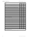
Power trouble
LED ON
Battery trouble
Batt yellow
LED ON
Missing or
Disconnected
1. Check battery connections.
Low or
damaged
battery
1. Remove batteries, check voltage across charger
output (17 to 19V), otherwise replace circuit board.
2. Reconnect batteries, measure battery voltage at
battery terminals. If voltage is less than 85% of rated
voltage, allow them to charge for 48 hours.
3. If problem persists, replace batteries.
Ground fault trouble
Earth yellow LED ON
1. Remove field wiring from main panel and optional
module(s) (if installed). Install dummy ELR (4.7K).
2. Remove both battery leads.
3. If trouble clears, connect one circuit at the time to
pin point the problem.
4. If trouble doesn’t clear, replace circuit board.
Yellow LED on
4XTM ON
4XTM
1. Move Municipal Box disconnect switch SW1 up.
OPT1, OPT2 jumper cut
1. Install optional module(s) or replace jumper if
module(s) is not used.
Municipal Box open circuit
1. Install dummy load if Municipal Box option isn’t
used.
2. Check Municipal Box wiring.
Any of the right column red LEDs
ON
Short on initiating circuit wiring
1. Remove field wiring and install ELR. If trouble
clears, look for faulty or incorrectly wired devices.
Disconnecting Municipal Box
switch ON 4XTM does not create
a trouble
Jumper for optional modules
isn’t cut
1. Cut associated jumper OPT1 or OPT2.
4XZM: associated LED doesn’t
activate for alarm, trouble or
supervisory conditions
Optional module trouble
1. Make sure module is properly installed.
2. Move disable switch SW1 on 4XZM to the left.
RZA-4X piezo doesn’t sound for
alarm, trouble or supervisory
conditions
4XLM
1. Make sure that 4XLM module is installed on J8.
2. Check field wiring.
Micro Fail yellow LED ON Microprocessor damaged
1. Replace circuit board.
All RZA-4X LEDs stay ON
Power wasn’t removed prior to
installation
1. Press system reset.
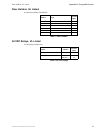
AC
Power
LED OFF
System trouble LED ON
Loss of main power
1. Check incoming power (TB5).
Damaged circuit breaker
1. Replace circuit board.
Micro Fail yellow LED ON Microprocessor damaged
1. Replace circuit board.