


PDRP-1001 Instruction Manual PN 50734:D0 04/06/01
37
Appendix A: Secondary Power Calculations
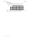
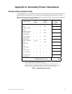
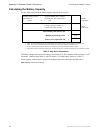
Standby Battery Requirements
The Standby Battery Current obtained in the table below represents the amount of current that must be
supplied by the secondary power source (batteries) to sustain control panel operation for one hour.
Note: The control panel will support the installation of one or two optional modules, including two of the same type of
module. Only one 4XLM can be included in this count.
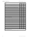
Table 1 Standby Battery Current
Device Type
# of
Devices
Current
(amps)
Total Current
(amps)
Main Circuit Board 1 X 0.088 =
0.088
4XZM
Zone Relay Module
[ ] X 0.008 =
4XTM
Transmitter
Module
[ ] X 0.011 =
•Reverse Polarity
Alarm output
[ ] X 0.005 =
•Reverse Polarity
Trouble output
[ ] X 0.005 =
RZA-4X/4XLM
Remote Annunciator
[ ]
(1 max)
X 0.019 =
4XMM
Meter Module
[ ] X 0.001 =
2-wire
Detector Heads
[ ] X
[ ]
1
1. Refer to the "Appendix B: Compatible Devices" on page 39 for smoke detector standby current.
=
4-wire
Detector Heads
[ ] X
[ ]
1
=
End-of-line Relays
2
2. Must use compatible listed Power Supervision Relay.
[ ] X [ ] =
Current Draw from
TB2 (nonalarm)
3
3. The total standby current must include both the resettable (TB1 - +24VR terminals) and
nonresettable (TB2 - +24VNR terminals) power. Caution must be taken to ensure that current
drawn from these outputs during alarm does not exceed maximum ratings specified.
[ ] X [ ] =
Standby Battery Current = amps