


Output Circuits 2. Installation
PDRP-1001 Instruction Manual PN 50734:D0 04/06/01
21
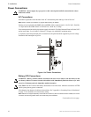
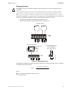
Releasing Circuits
CAUTION: To prevent accidential discharge, connect releasing devices after initial panel tests are
completed.
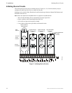
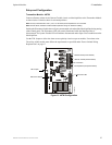
The control panel provides two Style Y (Class B) Releasing Circuits, which are nonpower-limited.
Note: All wiring must follow the requirements as specified under "Power-limited Wiring Requirements" on page 17.
Each circuit is capable of 1.5 amps of current. Total current drawn from both Releasing Circuits and both
NACs (see "Notification Appliance Circuits" on page 20) cannot exceed 2.25 amps.
• UL listed and FM approved releasing devices must be used.
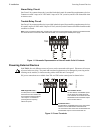
• Unused circuits must be connected with a dummy load as shown.
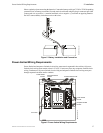
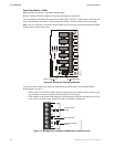
Figure 10 Releasing Circuits
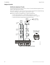
Wiring must be configured to maintain a minimum voltage of 20.4 VDC on releasing Circuits. Calculation
of maximum allowable resistance:
Where:
Rmax = maximum allowable resistance of wiring
Is = Solenoid current
!
TB2
TB2
Releasing Circuits
Canadian Applications
MRP44-rel.cdr
REL-4.7K
Unused Releasing Circuits
4.7K, 1/4-Watt ELR
PN 71252 (UL listed)
Rmax =
20.6 VDC – 20.4 VDC
Is