


2. Installation Cabinet Mounting
14
PDRP-1001 Instruction Manual PN 50734:D0 04/06/01
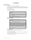
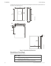
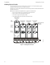
The figure below shows the exterior dimensions and mounting hole locations for the cabinet backbox and
dimensions of the optional trim ring:
Figure 2 Cabinet Mounting Dimensions
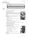
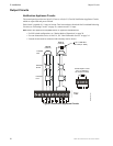
Reinstallation of Circuit Board
Reinstall the printed circuit board as follows:
Step Action
1 Position circuit board over stand-offs on backbox rail and secure with four
(4) phillips screws. Tighten securely.
2 Connect transformer wires to J1 connector on circuit board.
14.625”
(
37.15cm
)
16.125”
(40.96cm)
5.375”
(
13.65cm
)
16.00”
(
40.64cm
)
4.75”
(
12.07cm
)
14.50”
(36.83cm)
12.50”
(
31.75cm
)
9.50”
(24.13cm)
1.00”
(2.54cm)
1.00”
(2.54cm)
1.5”
(3.81cm)
16.125”
(40.96cm)
14.625”
(37.15cm)
MS44-cabdim.cdr
MS44-trimring.cdr