


Universal Digital Alarm Communicator - 411UDAC Appendix C: NFPA Standard-Specific Requirements
PDRP-1001 Instruction Manual PN 50734:D0 04/06/01
47
Universal Digital Alarm Communicator - 411UDAC
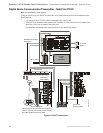
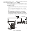
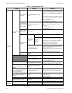
The following figure illustrates an example of Central Station/Remote Station Receiver or Protected
Premises Receiving Unit reporting using a 411UDAC. The relay contacts of the MRP-4424 may be used
to trip any dialer listed for Central Station/Remote Station services. For additional information refer to the
Instruction Manual for the 411UDAC.
• All connections between the control panel and the 411UDAC must be in conduit, less than 20 feet
(6.1 meters) in length in the same room.
• The PDRP-1001 Series is non suitable for transmission of a supervisory signal to the DACT.
• Any zone of the 411UDAC can be wired to function as alarm or trouble; the unit must be
programmed accordingly. In this example, Zone 1 is wired to the control panel’s alarm relay, Zone2
is wired to the control panel’s trouble relay, and Zone 3 is wired to the optional module’s supervisory
relay.
• AC power is supplied directly to the 411UDAC, not through the control panel. AC wiring for both
the 411UDAC and the control panel must be connected to the same AC branch circuit.
• End-of-Line Resistors must terminate all circuits. In this example, Zone 4 is unused and is
terminated at the board.
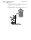
• When employing a DACT, place the JP1 jumper, on the control panel, as shown below. This directs
the panel to transmit all trouble conditions except AC LOSS. The DACT must be configured to
transmit AC power loss to the central station.
Figure 25 411UDAC Connections
TB2
TB4
TB1
RELAY 1
NO NC C
RELAY 2
NO NC C
NAC
B+ B-
ZONE 1
B+ B-
ZONE 4
B+ B-
ZONE 2
B+ B-
ZONE 3
B+ A+ A- B-
+12V PWR
+ -
PH1
PH2
Trouble
Alarm
Secondary Phone Line
Primary Phone Line
Modular Cable
P/N MCBL-6
Supervisory
Control Panel
4XZM Zone
Relay Module
MS44-411.cdr
Zone 1
Zone 2
Zone 3
411 UDAC
Jumper