


Optional Modules 2. Installation
PDRP-1001 Instruction Manual PN 50734:D0 04/06/01
25
Setup and Configuration
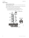
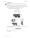
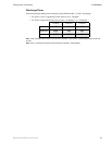
Transmitter Module - 4XTM
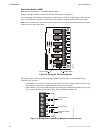
Connect a Remote Alarm circuit, Remote Trouble circuit or a Municipal Box to the Transmitter Module
as shown below. Polarities shown in activated positions.
Note: Dummy load terminals 6 and 7 (4.7K, 1/4 W resistor) if Municipal Box is not connected.
Note: Remote Alarm, Remote Trouble and Municipal Box wiring can leave the building.
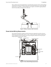
Pushing the Disconnect Switch down will prevent unwanted activation of the Municipal Box during testing
of the control panel. The Disconnect LED will remain illuminated while the Municipal Box is
disconnected. The System Trouble LED will indicate disconnected and/or Open Circuit conditions on the
Municipal Box.
Cut the TBL Jumper to allow the alarm reverse polarity circuit to open on trouble, if no alarm exists.
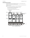
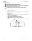
The wiring of this module must follow the requirements as specified under "Power-limited Wiring
Requirements" on page 17.
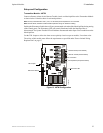
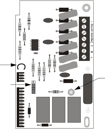
Figure 15 4XTM Configuration
TB1
TBL
J1
J2
4XTMF.cdr
TBL Jumper
Disconnect Switch
Disconnect LED
Remote Alarm (Power-limited)
Remote Trouble (Power-limited)
Municipal Box (Nonpower-limited)
No Connection
+
–
+
–
+
–