


Power-limited Wiring Requirements 2. Installation
PDRP-1001 Instruction Manual PN 50734:D0 04/06/01
17
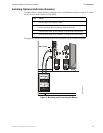
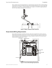
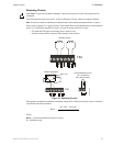
Observe polarity when connecting the batteries. Connect the battery cable (p/n 75203 or 75202, depending
on terminal size of battery) to terminal J9 on the main circuit board using the plug-in connector provided.
Connect red wire to positive (+) terminal and black wire to negative (–) terminal on opposing batteries.
Do NOT connect battery interconnect wire at this time.
Figure 5 Battery Installation and Connection
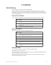
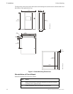
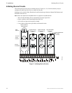
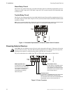
Power-limited Wiring Requirements
Power-limited and nonpower-limited circuit wiring must remain separated in the cabinet. All power-
limited circuit wiring must remain at least 0.25 in (6.35 mm) away from any nonpower-limited circuit
wiring. Furthermore, all power-limited circuit wiring and nonpower-limited circuit wiring must pass
through separate knockouts and/or conduits.
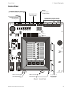
Figure 6 Power-limited Wiring Requirements
J3
J9
J2
AMP
TB5
MS44-BATconn.cdr
GEN
ALM2
TONE
SILENCE
ALARM
SILENCE
ALARM
ACT IVATE
SYSTEM
RESET
AC POWER
SY STEM
ALARM
ALARM T EST
SUPERVISORY
SY STEM
TROUBLE
CIRCUIT
TROUBLE
ALARM
SILENCED
POWER
TROUBLE
ZONE 1
ZONE 2
ZONE 3
ZONE 4
SW1
TB1
TB2
TB3
TB4
JP1
SUPV 1
SUPR 2
GEN
ALM1
J4
J5
J7
J8
OPT1
OPT2
J1 0
J3
J9
J2
AMP
J1
TB5
OUT#1
B+ A + A– B–
OUT#3
B+ B –
OUT#4
B+ B –
ALARM
NO NC C
OUT#2
B+ A + A– B–
IN # 1
B+ A + A– B–
IN # 2
B+ A + A– B–
IN # 3
B+ A + A– B–
IN # 4
B+ A + A– B–
TB1
LATCH
DISABLE
J2
TB1
TBL
J1
J2
7 6 5 1
POWER LIMITED
AC Power
MRP44-plwiring.cdr
Power-limited
Circuits
Nonpower-limited
Circuits
Power-limited Circuits
Nonpower-limited
Circuits
Power-limited
Circuits