


2. Installation Setting Mode of Operation
28
PDRP-1001 Instruction Manual PN 50734:D0 04/06/01
Setting Mode of Operation
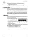
Select operating mode by setting the SW1 DIP switches as described below.
After any changes are made to the configuration of the switches, the panel must be reset.
For Canadian use, refer to "Sprinkler Supervisory Tracking" on page 34.
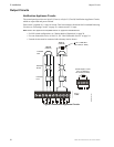
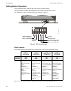
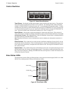
Figure 19 DIP Switch Settings
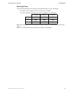
Basic Program
Select the desired mode of operation and set DIP Switches 1 and 2 per the appropriate column.
Note: Output 1 and 2 refer to Notification Appliance Circuits; Output 3 and 4 refer to Releasing Circuits.
Mode 1
Two Zone
Single Hazard
Mode 2
Cross Zone
Single Hazard
Mode 3
Combined Release
Dual Hazard
Mode 4
Split Release
Dual Hazard
Switch 1
Switch 2
OFF
OFF
ON
OFF
OFF
ON
ON
ON
Output 1 & 3 -
Activated by an
alarm on either IDC
1 or 2.
Output 2 -
Activated by a
waterflow alarm on
IDC 3.
Output 4 -
Activated by a
supervisory condition
on IDC 4.
Output 1 -
Activated by an
alarm on either IDC
1 or 2.
Output 2 -
Activated by a
waterflow alarm on
IDC 3.
Output 3 -
Activated by alarms
on both IDC 1 and 2.
Output 4 -
Activated by a
supervisory condition
on IDC 4.
Output 1 -
Activated by an
alarm on either IDC
1 or 2 or a waterflow
alarm on IDC 3.
Output 2 -
Activated by a
supervisory condition
on IDC 4.
Output 3 & 4 -
Activated by an
alarm on either IDC
1 or 2.
Output 1 -
Activated by an
alarm on either IDC
1 or 2 or a waterflow
alarm on IDC 3.
Output 2 -
Activated by a
supervisory condition
on IDC 4.
Output 3 -
Activated by an
alarm on IDC 1.
Output 4 -
Activated by an
alarm on IDC 2.
SW1
MS44-dipsw.cdr
Basic Programming
Switch 1: Cross Zone
Switch 2: Dual Hazard
Discharge Timer
Switch 3: Discharge Timer
Switch 4: Discharge Timer
Switch 5: Discharge Timer
Not Used