


2. Installation Optional Modules
24
PDRP-1001 Instruction Manual PN 50734:D0 04/06/01
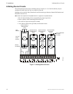
Installation - Lower Position
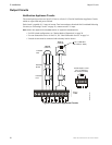
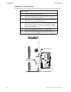
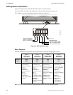
To install either the 4XTM, 4XZM or 4XLM module in the lower position follow these instructions:
Figure 14 Module Installation - Lower Position
Step Action
1 Cut jumper ‘OPT2’ on main circuit board.
2 Remove the lower-right screw securing the main board to the lower rail.
Replace with a stand-off and tighten securely.
3 Insert one stand-off into the other hole located on the right-side edge of the
main board. Secure with nut and tighten securely.
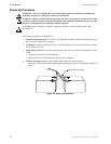
4 Align the pins of J8 (and J7) connectors on the main board with the holes on
the underside of the J2 (and J1) connector on the optional board. Carefully
press down on the optional board until the pins are through the connectors
and it rests on the stand-offs.
5 Secure optional board to stand-offs with screws. Tighten securely.
6 Affix the terminal identification label (provided with the module) on the
back surface of the backbox, aligning it with the terminals on the module.
TB4
J4
J5
J7
J8
OPT1
OPT2
J10
B–
IN #2
B+ A+ A– B–
IN #3
B+ A+ A– B–
IN #4
B+ A+ A– B–
TB1
J2
MS44-instmod2.cdr
Install Stand-offs here
OPT2 - Cut prior to
installation of module