


Turbomachinery Package Specification Taurus 60 Compressor Set and Mechanical Drive
8 Fuel System
8.1 General Description
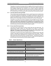
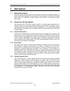
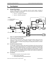
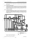
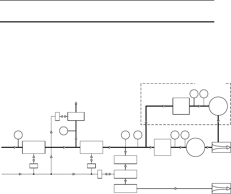
The fuel system (Figure 12), in conjunction with the control system, includes all
necessary components to control ignition and fuel flow during all modes of operation.
There are two available configurations:
• Gas fuel – conventional combustion
• Gas fuel – SoLoNOx combustion
MAIN
FUEL
CONTROL
VALVE
TPRT
PRIMARY
SHUT OFF
VALVE
TORCH
REGULATOR
TORCH SHUT
OFF VALVE
VENT
VALVE
V
S
VS VS
TP
TP
MAIN FUEL
MANIFOLD
GAS FUEL
INJECTOR
TORCH
V
S
TORCH
REGULATOR
SECONDARY
SHUT OFF
VALVE
PILOT
FUEL
CONTROL
VALVE
PILOT FUEL
MANIFOLD
GAS VENT
AIR
FUEL
LEGEND
TP = PRESSURE TRANSMITTER
TPD = DIFFERENTIAL PRESSURE TRANSMITTER
RT = RTD (TEMPERATURE)
VS = VALVE SOLENOID
ONLY FOR SOLONOX
TP TP
TP TP
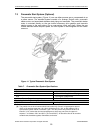
Figure 12. Typical Fuel System Schematic
8.1.1 Conventional Combustion System
Solar’s conventional combustion system uses fuel injectors equally spaced around the
combustor to inject fuel into the combustion chamber. The fuel injected into the
combustion chamber is controlled during starting and steady-state operation to maintain
stable combustion.
8.1.2 SoLoNOx Combustion System
The SoLoNOx combustion system uses special fuel injectors with main and pilot fuel
ports. The fuel injected through these ports is controlled during starting and steady-state
operation to maintain stable combustion and minimize the formation of nitrous oxides
(NOx), carbon monoxide (CO), and unburned hydrocarbon (UHC) emissions. To further
regulate emission levels, combustion airflow is regulated using a bleed valve mounted on
the combustor case. The SoLoNOx combustion system also includes an additional inlet
gas filter/coalescer for mounting offskid.
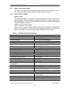
8.1.3 Fuel System
For conventional combustion, the fuel system includes:
• Supply pressure transmitter
• Pilot air operated primary gas fuel shutoff valve
© 2009 Solar Turbines Incorporated. All rights reserved. TPS60CSMD/309
26