


Turbomachinery Package Specification Taurus 60 Compressor Set and Mechanical Drive
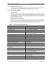
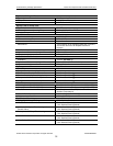
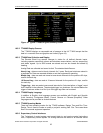
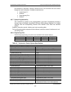
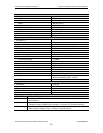
The system is configurable from the control processor. It detects preprogrammed alarm
and shutdown levels. See the specification tables for a list of monitored channels.
10.3.5 Backup Shutdown System
The backup shutdown system shuts the package down in a safe and orderly manner
without damage to the equipment in the event of a failure in the primary system. The
control processor is monitored by both an internal watchdog circuit and by an external
watchdog device. If either circuit detects a processor failure, the backup system takes
control. It depressurizes the compressor (if applicable), closes the fuel valves, and
initiates a post lube cycle to protect the turbine bearings. Once a backup shutdown is
initiated, operation can only be restored manually from the control panel after all faults
have been cleared. The emergency stop push-button switches are wired to both the
primary and backup systems.
10.3.6 Fire and Gas System
Enclosed packages require fire and gas control protection. The Eagle Quantum Premier
system from Det-Tronics detects combustible gas and/or fire inside the enclosure based
on inputs from gas, thermal, and optical flame detectors. If fire is detected, the system
releases an extinguishing agent into the enclosure. If a fire or an unacceptable gas level
is detected, the system instructs the Turbotronic control processor to initiate a package
shutdown. The system is also wired directly to the backup shutdown system. See
Enclosure Section 12 for a more complete description.
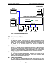
10.3.7 Control System Power Supplies
The control system operates on 24 VDC power. The standard battery charge system
provides 120 VDC power to the control system. The control system includes a 120 to 24
volt DC-to-DC converter to supply 24 VDC power to the control system. For a more
detailed description of the battery charger system, refer to Section 15, Accessory
Equipment.
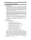
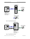
10.3.8 Interconnect Cables – Offskid Control Systems
With the offskid controls configuration, interconnect cabling must be provided between
the package skid and the control console. This cabling is not in Solar’s standard scope of
supply. Solar’s standard wiring recommendations are based on a cable length of 76 m
(250 ft). For interconnects over 76 m, the wire gages must be adjusted to maintain the
equivalent loop resistance of the Turbotronic 4 standard design, and must not exceed a
5% voltage drop. This may require a larger wire gage. For interconnects over 76 m, low
capacitance wire (0.03 μF/m; 0.01 μF/ft) must be used for the speed signal and vibration
cables.
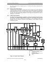
10.4 System Monitoring and Control Functions
The control system provides sequencing control during gas turbine startup, steady state
operation, and shutdown. Protective functions are provided during all stages of operation.
10.4.1 Starting and Loading
The Start command initiates the sequence. Prior to rotation, the lube oil pump undergoes
a test cycle, the enclosure fans (if applicable) are started, and the fuel valves undergo a
test cycle with fuel pressure verification.
The starter then rotates the gas turbine and the compressor develops airflow to purge
any accumulated gas in the gas turbine, air inlet, and exhaust duct. The purge cycle is
tailored to the exhaust duct volume.
When the engine has reached the required speed and temperature, a small amount of
fuel is introduced into the combustor from the gas torch and ignited by the ignitor plug.
© 2009 Solar Turbines Incorporated. All rights reserved. TPS60CSMD/309
37