


Turbomachinery Package Specification Taurus 60 Compressor Set and Mechanical Drive
15 Accessory Equipment
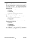
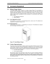
15.1 Battery Charger System
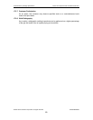
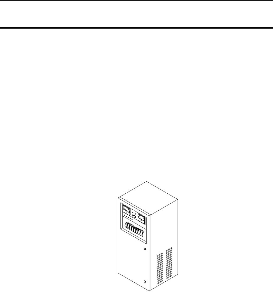
The battery charger system consists of a battery charger (Figure 27) and batteries to
provide 120 VDC emergency power to the control console, fuel valve, bleed valve and
variable guide vane actuators, and the DC backup lube oil pump. The control console
120 to 24 volt DC-to-DC converter provides 24 VDC power for the control system. The
battery charger system is designed for indoor installation in a nonhazardous area. Battery
options include:
• Valve Regulated Lead Acid
• Nickel Cadmium
15.1.1 Valve Regulated Lead Acid
The batteries are mounted on a freestanding two-tier, two-row rack. The batteries are
shipped fully charged and ready for use.
15.1.2 Nickel Cadmium
The batteries are mounted on a freestanding, four-step rack. The batteries are shipped
wet, fully charged, and ready for use.
Figure 27. Typical Battery Charger
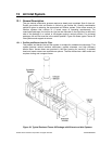
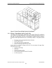
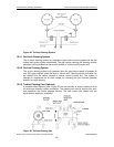
15.2 Turbine Cleaning System
The optional turbine compressor cleaning system (Figure 28) facilitates periodic cleaning
of the turbine compressor. The cleaning system is designed for use in salt-laden or dusty
environments or where compressor contamination from hydrocarbon vapors is possible.
The turbine compressor cleaning system is composed of the following systems:
• On-crank cleaning system
• On-line cleaning system
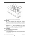
Both cleaning systems are independent of each other and include a separate distribution
manifold with pressure atomizing spray nozzles in the engine air inlet collector, onskid
piping, strainer, and solenoid shutoff valves to deliver water or approved cleaning fluid to
the manifold. Both systems require an external source of clean-filtered air to pressurize
the cleaning solutions.
© 2009 Solar Turbines Incorporated. All rights reserved. TPS60CSMD/309
62