


Turbomachinery Package Specification Taurus 60 Compressor Set and Mechanical Drive
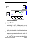
11 Compressor Control and Monitoring
11.1 General Description
The following sections outline the control and monitoring options available for
compressors and mechanical drives.
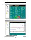
11.1.1 Process Control
The process control options provide unit control based on the gas compressor suction
pressure, discharge pressure, and flow (or combinations of these parameters). Local and
remote setpoint adjustments are included. If prime, Solar will provide the necessary
transmitters. If the driven equipment supplier is prime, the following input signals are
required depending on the type of control:
• 4-to-20 mA pressure signal
• 4-to-20 mA flow element differential pressure
• Temperature at flow element (100-ohm platinum RTD preferred)
11.1.2 Suction Pressure, Discharge Pressure, and Flow Shutdowns
The basic package may be supplied with driven equipment suction pressure, discharge
pressure, and flow transmitters and associated control system logic to provide for
indication, warning alarm, and unit shutdown when the suction pressure, discharge
pressure, or flow exceeds a preset value.
• Suction pressure transmitter – shipped separately for installation by purchaser
• Discharge pressure transmitter – shipped separately for installation by
purchaser
• Suction flow transmitter – shipped separately for installation by purchaser
11.1.3 Gas Compressor Surge Detection System
The surge detection system detects gas compressor discharge pressure pulsations and
initiates a gas turbine shutdown if pulsations exceed a preset value within a
predetermined time period. For applications without an anti-surge control system supplied
by Solar, a gas compressor surge detection system is recommended.
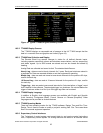
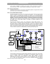
11.1.4 Anti-Surge Control
Surge at a given gas compressor speed is caused by excessive head across the gas
compressor (isentropic head) for a given suction flow rate. Therefore, surge in the gas
compressor may be controlled by decreasing the head across the gas compressor and/or
by increasing the flow rate of the gas to the suction side of the gas compressor. The anti-
surge control system prevents surge by modulating a surge control (bypass) valve to
lower head and increase suction flow. A typical system consists of pressure and
temperature transmitters on the gas compressor suction and discharge lines, a flow
differential pressure transmitter across the suction flowmeter, an algorithm in the control
system, and a surge control valve with corresponding accessories to keep the gas
compressor from going into surge.
The following components and information are required from the purchaser in order to
facilitate the surge control system design and onsite operation:
• Expected gas compressor operating conditions range for suction pressure (P
1),
suction temperature (T
1), discharge pressure (P2), flow and gas specific gravity
• Flow meter specification sheet
© 2009 Solar Turbines Incorporated. All rights reserved. TPS60CSMD/309
44