


Turbomachinery Package Specification Taurus 60 Compressor Set and Mechanical Drive
10 Turbotronic 4 Control System
10.1 General Description
The Turbotronic 4 control system controls and monitors the turbomachinery package
including the gas turbine and driven equipment. The system scope can be expanded to
include monitoring and/or control of balance of plant equipment that is directly package
related. The system architecture is based on a Rockwell Automation/Allen-Bradley
hardware and software platform and includes fully integrated driven equipment, vibration
and, when required, fire and gas monitoring and control subsystems. The primary control
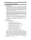
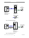
system components may be mounted either “onskid” on the package skid (Figure 14) or
“offskid” in a freestanding console (Figure 15).
The onskid design is approved for use in areas classified as Class I, Group D, Division 2,
by the National Electrical Code (NEC) and in areas classified as Zone 2, Group IIA, under
the Committee for Electrotechnical Standardization (CENELEC) standards. An auxiliary
display and monitoring system is available, mounted in either an optional console or a
desktop computer. Control connections between the package and the auxiliary display
are through a pair of redundant network cables. A limited set of hardwired cables may
also be required depending on the configuration.
For NEC Division 1 and CENELEC Zone 1 applications, the offskid design must be used.
This design requires a full set of hardwired interconnect cables between the package, the
control console, the motor control center (MCC) and any other controlled items.
An independent backup shutdown system provides additional protection. This shuts the
package down in a safe and orderly manner in the event of malfunction of the primary
control system.
10.2 System Architecture
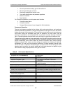
Key system components include:
• ControlLogix controller (Allen-Bradley)
• RSLogix 5000 programming software (Rockwell Automation)
• 1794 Flex I/O input/output modules (Allen-Bradley)
• 1701 FieldMonitor vibration monitoring system (Bently Nevada)
• ControlNet network (ControlNet International)
• TT4000 offskid display and monitoring system (Solar Turbines)
• Offskid operator control panel* (Solar Turbines)
• TT4000S onskid local operator interface (Solar Turbines)
• Onskid operator control panel (Solar Turbines)
• Fire and gas monitoring and control system (Det-tronics)
• Independent backup shutdown system (Solar Turbines)
* Included with standard offskid configuration, optional with onskid configuration
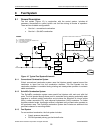
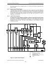
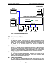
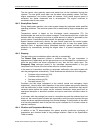
Figure 16 provides an overview of the principle control system elements. The ControlNet
network provides primary communications between components. Hardwire backup is
provided for critical circuits. The TT4000S and onskid operator panel are located on the
package skid. The TT4000 and offskid operator panel are located in a non-hazardous
area such as a control room. The variable speed frequency drive (VFD) for the start
motors is typically located in a motor control center. All other components are rated NEC
Class 1, Division 2 or CENELEC Zone 2 for hazardous area duty and are located on the
package skid for the onskid controls configuration or in a console for the offskid
configuration.
© 2009 Solar Turbines Incorporated. All rights reserved. TPS60CSMD/309
34