


Turbomachinery Package Specification Taurus 60 Compressor Set and Mechanical Drive
of the panels in decibels is available upon request. Further information is available in
Solar’s publication SPNP, “Noise Prediction Guidelines for Industrial Gas Turbines.”
12.2.8 Exterior Connections
Connections for oil vent line, fire and gas suppression systems, and gas turbine air inlet
and exhaust are terminated outside the enclosure.
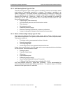
12.2.9 Fire and Gas Detection System
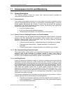
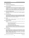
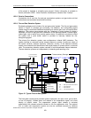
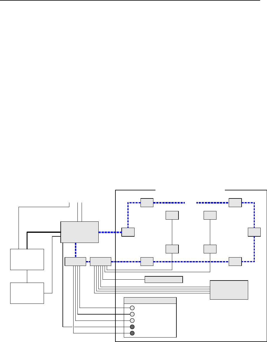
Enclosed packages must include a fire and gas control system. The fire and gas system
shown in Figure 21 provides gas monitoring, fire detection, and extinguishing agent
release using an advanced distributed architecture to monitor gas, heat, and optical flame
detectors. The system communicates with the Turbotronic 4 control system to initiate a
shutdown if a fire or a high gas level is detected. On the package exterior, indicator lights,
strobe lights, and an alarm horn provide system status. A keyswitch is provided to inhibit
the system and a push button switch is provided to manually release the fire-
extinguishing agent.
The primary fire detection system uses multispectrum infrared (MIR) detectors. The
system includes an automatic optical integrity feature to provide a continuous check of
the optical surfaces, detector sensitivity, electronic circuitry of the detector-controller
system, and automatic fault identification with digital display of system status in numerical
code. The secondary detection system consists of rate-compensated thermal detectors.
The two detection systems act independently in detecting and reporting a fire.
OPERATOR PANEL
EQP
DCIO
MIR MIR
MIRMIR
IR IR
TD TD
TDTD
Turbotronic 4
Control
Processor
Turbotronic 4
Back-up
Shutdown
System
Turbomachinery Package
To / From Customer
Supervisory System
STROBES / HORN
FIRE
SUPPRESSION
SYSTEM
AUTO
INHIBIT
DISCHARGED
AUTO / INHIBIT
MANUAL RELEASE
LON
DCIO
MIR = Multi-spectrum IR Flame Detector
TD = Thermal Detector
IR = IR Gas Detector
LON = Local Operating Network
ControlNet
Figure 21. Typical Fire and Gas System
The fire system control panel provides system supervision (for open circuit, ground fault,
or loss of integrity), initiates alarm and release of fire suppression agent, and visual
display of system status. The suppression system agent release is activated
automatically with release solenoids located on the fire suppression skid. The optional
CO
2
or water mist suppression system can also be activated manually by switches
© 2009 Solar Turbines Incorporated. All rights reserved. TPS60CSMD/309
49