


Specifications
TDS 500D, TDS 600B & TDS 700D Performance Verification and Specifications
2–3
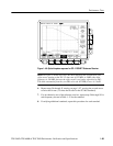
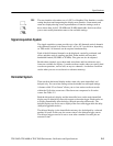
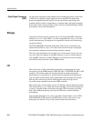
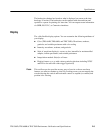
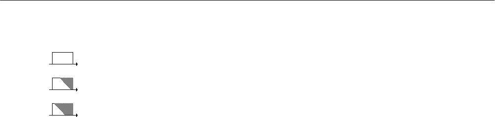
The user interface also makes use of a GUI, or Graphical User Interface, to make
setting functions and interpreting the display more intuitive. Some menus and
status are displayed using iconic representations of function settings, such as
those shown here for full, 250 MHz and 20 MHz bandwidth. Such icons allow
you to more readily determine status or the available settings.
Signal Acquisition System
The signal acquisition system provides up to four, full-featured vertical channels
with calibrated vertical scale factors from 1 mV to 10 V per division, depending
on TDS model. All channels can be acquired simultaneously.
Each of the full-featured channels can be displayed, vertically positioned, and
offset, and their vertical coupling specified. Some models can have their
bandwidth limited (250 MHz or 20 MHz). Fine gain can also be adjusted.
Besides these channels, up to three math waveforms and four reference wave-
forms are available for display. (A math waveform results when you specify dual
waveform operations, such as add, on any two channels. A reference waveform
results when you save a waveform in a reference memory).
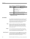
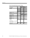
Horizontal System
There are three horizontal display modes: main only, main intensified, and
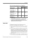
delayed only. You can select among various horizontal record length settings.
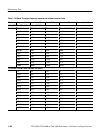
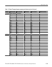
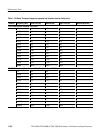
A feature called “Fit to Screen” allows you to view entire waveform records
within the 10 division screen area. Waveforms are compressed to fit on the
screen. See Table 2–2.
Both the delayed only display and the intensified zone on the main intensified
display may be delayed by time with respect to the main trigger. Both can be set
to display immediately after the delay (delayed runs after main mode). The
delayed display can also be set to display at the first valid trigger after the delay
(delayed-triggerable modes).
The delayed display (or the intensified zone) may also be delayed by a selected
number of events. In this case, the events source is the delayed-trigger source.
The delayed trigger can also be set to occur after a number of events plus an
amount of time.
GUI