


Typical Characteristics
2–30
TDS 500D, TDS 600B & TDS 700D Performance Verification and Specifications
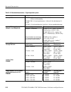
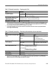
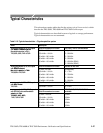
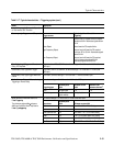
Table 2–16: Typical characteristics — Signal acquisition system (cont.)
Name Description
S
te
p
Res
p
o
n
se
S
ettli
n
g
E
rr
o
r
s
livei
S ep ampli e
Settling error (%)
3
at
Vo
l
ts/D
iv
s
e
tt
i
ng ±
S
t
ep
ampli
tud
e
20 ns 100 ns 20 ms
1 mV/div – 100 mV/div ≤2 V ≤0.5% ≤0.2% ≤0.1%
101 mV/div – 1 V/div ≤20 V ≤1.0% ≤0.5% ≤0.2%
1.01 V/div – 10 V/div ≤200 V ≤1.0% ≤0.5% ≤0.2%
S
te
p
Res
p
o
n
se
S
ettli
n
g
E
rr
o
r
s
DD
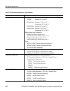
10 mV/div – 100 mV/div ≤1.5 V ≤0.5% ≤0.2% ≤0.1%
T
D
S 794
D
101 mV/div – 1 V/div ≤3 V ≤1.0% ≤0.5% ≤0.2%
1
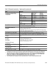
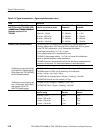
The limits given are for the ambient temperature range of 0_C to +30_C. Reduce the upper bandwidth frequencies by
5 MHz for the TDS 600B or by 2.5 MHz for the TDS 500D/700D for each _C above +30_C.
2
The numbers given are valid 0_C to +30_C and will increase as the temperature increases due to the degradation in
bandwidth. Rise time is calculated from the bandwidth. It is defined by the following formula:
Note that if you measure rise time, you must take into account the rise time of the test equipment (signal source, etc.) that
you use to provide the test signal. That is, the measured rise time (RT
m
) is determined by the instrument rise time (RT
i
) and
the rise time of the test signal source (RTgen) according to the following formula:
TDS 600B Rise Time (ns) +
450
BW (MHz)
RT
m
2
+ RT
i
2
) RT
gen
2
TDS 500Dń700D Rise Time (ns) +
400
BW (MHz)
3
The values given are the maximum absolute difference between the value at the end of a specified time interval after the
midlevel crossing of the step and the value one second after the midlevel crossing of the step, expressed as a percentage
of the step amplitude.
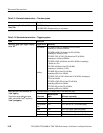
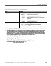
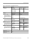
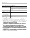
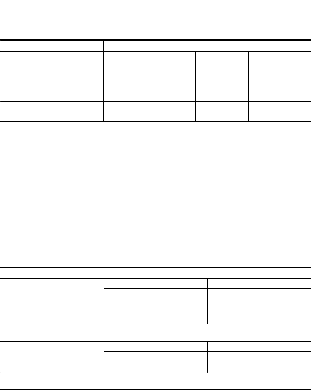
Table 2–17: Typical characteristics — Triggering system
Name Description
Acc
u
rac
y,
Tri
gg
er
Level
o
r
T
h
re
sho
l
d, DC
ple
Trigger source Accuracy
Cou
ple
d
(for signals having rise and fall times
≥ 20 ns)
Any Channel
Auxiliary
±((2% × | Setting – Net Offset |)
+ (0.3 div × Volts/div Setting ) + Offset
Accuracy)
Not calibrated or specified
Input, Auxiliary Trigger
The input resistance is ≥1.5 kW; the maximum safe input voltage is
±20 V (DC + peak AC).
Tr
igge
r P
ositio
n
E
rr
o
r,
E ge igge i g
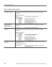
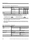
Acquisition mode Trigger-position error
1,2
E
d
ge
Tr
igge
r
i
n
g
Sample, Average
Envelope
±(1 Waveform Interval + 1 ns)
±(2 Waveform Intervals + 1 ns)
Holdoff, Variable, Main Trigger
For all Time/Division ranges, the minimum holdoff is 250 ns and the maximum holdoff is 12
seconds. The minimum resolution is 8 ns for settings ≤ 1.2 ms.