


Performance Tests
TDS 500D, TDS 600B & TDS 700D Performance Verification and Specifications
1–61
H Leave the Main trigger system triggered on the positive slope of the
waveform before proceeding to the next check.
H Press the main-menu button Source; then press the side-menu button
–more– until CH 1 appears. Press CH 1.
4. Confirm that the Main and Delayed trigger systems are within sensitivity
limits (full bandwidth):
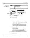
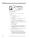
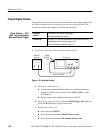
a. Hook up the test-signal source: Disconnect the hookup installed in
step 1. Connect the signal output of a high-frequency sine wave
generator to CH 1. Some TDS models need a high frequency
(>500 MHz) generator; see footnotes 1 and 4 in Table 1–1.
b. Set the Main and Delayed Horizontal Scales:
H Set the horizontal SCALE to 500 ps for the M (Main) time base.
H Press HORIZONTAL MENU. Now press the main-menu button
Time base; then press the side-menu button Delayed Triggerable.
H Press the side-menu button Delayed Only.
H Set the horizontal SCALE to 500 ps for the D (Delayed) time base.
Press the side-menu button Main Only.
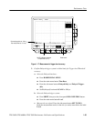
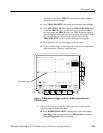
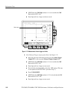
c. Display the test signal:
H Set the generator frequency to full bandwidth as follows:
TDS 794D: 2 GHz
TDS 580D, 680B, 684B, & 784D: 1 GHz
TDS 520D, 540D, 620B, 644B, 724D, & 754D: 500 MHz
H Set the test signal amplitude for about five divisions on screen. Now
fine adjust the generator output until the CH 1 Amplitude readout
indicates the amplitude is 500 mV. (Readout may fluctuate around
500 mV).
H Disconnect the leveling head at CH 1 and reconnect it to CH 1
through a 5X attenuator.
d. Repeat step 4, substeps b and c only, since only the full bandwidth is to
be checked here.
NOTE. You just checked the trigger sensitivity. If desired, you may repeat steps 1
through 4 for the other channels (CH2, CH3, and CH4).
5. Disconnect the hookup: Disconnect the cable from the channel last tested.