


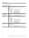

Warranted Characteristics
TDS 500D, TDS 600B & TDS 700D Performance Verification and Specifications
2–21
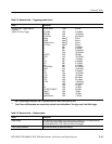
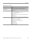
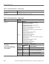
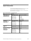
Table 2–10: Warranted characteristics — Signal acquisition system (cont.)
Name Description
A
n
al
og
Ba
ndw
i
dth, DC-
5
0 W Cou
ple
d
and Bandwidth selection is FULL,
TDS 500D/700D
Volts/Div
TDS 520D, 540D,
724D & 754D
Bandwidth
2
TDS 580D &
TDS 784D
Bandwidth
2
10 mV/div – 1 V/div DC – 500 MHz DC – 1 GHz
5 mV/div – 9.95 mV/div DC – 500 MHz DC – 750 MHz
2 mV/div – 4.98 mV/div DC – 500 MHz DC – 600 MHz
1 mV/div – 1.99 mV/div DC – 450 MHz DC – 500 MHz
Volts/Div
TDS 794D
Bandwidth
2
10 mV/div – 1 V/div DC – 2 GHz
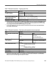
Crosstalk (Channel Isolation) ≥100:1 at 100 MHz and ≥30:1 at the rated bandwidth for the channel’s Volt/Div setting,
for any two channels having equal Volts/Div settings
Delay Between Channels, Full
Bandwidth
TDS 600B: ≤100 ps for any two channels with equal Volts/Div and Coupling settings and
both channels’ deskew values set to 0
TDS 500D/700D: ≤50 ps for any two channels with equal Volts/Div and Coupling settings
and both channel deskew values set to 0.0 ms.
Input Impedance, DC–1 MW Coupled 1 MW ±0.5% in parallel with 10 pF ±3 pF (DC–50 W Coupled only on TDS 794D)
Input Impedance, DC–50 W Coupled
50 W ±1% with VSWR ≤1.3:1 from DC – 500 MHz, ≤1.5:1 from 500 MHz – 1 GHz
Input Impedance, DC–50 W Coupled
TDS 794D
50 W ±1.25% with VSWR ≤1.5:1 from 100 MHz – 1 GHz, VSWR ≤1.7:1 from 1 GHz –
2 GHz
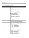
Input Voltage, Maximum,
DC–1 MW,
AC–1 MW, or
GND Coupled
(DC–50 W or GND Coupled
TDS 794D only)
TDS 600B: ±300 V CAT II, 400 V peak;
derate at 20 dB/decade above 1 MHz
TDS 500D/700D: ±300 V CAT II, 400 V peak;
derate at 20 dB/decade above 1 MHz
Input Voltage, Maximum, DC-50 W or
AC–50 W Coupled
5 V
RMS
, with peaks ≤ ±30 V
Input Voltage, Maximum, DC-50 W
Coupled TDS 794D
5 V
RMS
, with peaks ≤ ±20 V
Lower Frequency Limit, AC Coupled ≤10 Hz when AC–1 MW Coupled; ≤200 kHz when AC–50 W Coupled
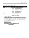
3
1
Net Offset = Offset – (Position × Volts/Div). Net Offset is the nominal voltage level at the oscilloscope input that
corresponds to the center of the A-D converter’s dynamic range. Offset Accuracy is the accuracy of this voltage level.
2
The limits given are for the ambient temperature range of 0_C to +30_C. Reduce the upper bandwidth frequencies by
5 MHz for the TDS 600B, by 2.5 MHz for the 500 MHz TDS 500D/700D models, by 5 MHz for the 1 GHz TDS 500D/700D
models, and by 10 MHz for the 2 GHz TDS 500D/700D models for each _C above +30_C.
3
The AC Coupled Lower Frequency Limits are reduced by a factor of 10 when 10X passive probes are used.