


Performance Tests
TDS 500D, TDS 600B & TDS 700D Performance Verification and Specifications
1–65
3. Confirm CH 3 (AUX 1 on some TDS models) output is within limits for gain:
a. Measure gain:
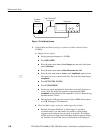
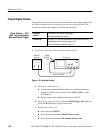
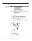
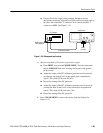
H Move the precision 50 W cable from the rear-panel DELAYED
TRIGGER OUTPUT BNC to the rear-panel CH 3/AUX 1 BNC
(SIGNAL OUT on some models).
H Push TRIGGER MENU.
H Press the main-menu button Source.
H Press the side-menu button Ch3.
(Ax1 on some TDS models)
H Set vertical SCALE to 100 mV.
H Press SET LEVEL TO 50%.
H Press MEASURE; then press the main-menu button Select
Measrmnt for Ch2.
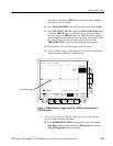
H Repeatedly press the side-menu button –more– until Pk-Pk appears
in the side menu (its icon is shown at the left). Press the side-menu
button Pk-Pk.
H Press CLEAR MENU.
b. Check against limits: (Skip the first four subparts of this substep for the
TDS 794D only.)
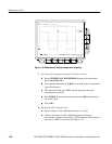
H CHECK that the readout Ch2 Pk-Pk is between 80 mV and 120 mV,
inclusive, for the TDS 600B or is between 88 mV and 132 mV,
inclusive, for the TDS 500D/700D.
H Enter voltage on test record.
H Press VERTICAL MENU; then press the side-menu button W to
toggle to the 50 W setting.
H Press CLEAR MENU.
H CHECK that the readout Ch2 Pk-Pk is between 40 mV and 60 mV,
inclusive, for the TDS 600B or is between 44 mV and 66 mV,
inclusive, for the TDS 500D/700D.
H Enter voltage on test record.
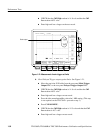
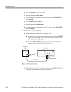
4. Disconnect the hookup: Disconnect the cables from the channel inputs and
the rear panel outputs.