


Typical Characteristics
2–32
TDS 500D, TDS 600B & TDS 700D Performance Verification and Specifications
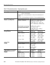
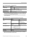
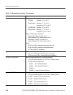
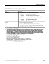
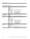
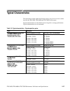
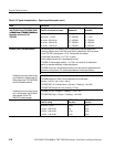
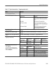
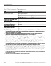
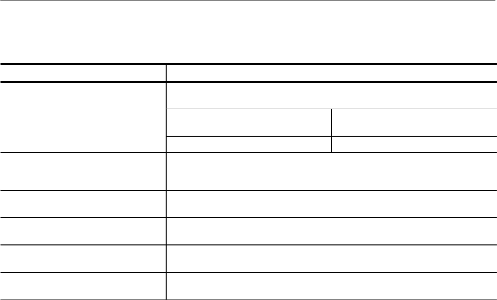
Table 2–17: Typical characteristics — Triggering system (cont.)
Name Description
Setup/Hold Time Violation Trigger,
Minimum Clock Pulse Widths
For vertical settings > 10 mV/div and ≤ 1 V/div at the BNC input,
the minimum requirements are:
Minimum Pulse Width,
Clock High
Minimum Pulse Width,
Clock Low
User Hold Time + 2.5 ns
9
2 ns
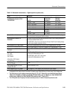
Input Signal Sync Amplitude for Stable
Triggering, HDTV and FLEXFMT modes
(Option 05 Video Trigger)
All field selections: 0.6 division to 4 divisions
Jitter for HDTV mode
(Option 05 Video Trigger)
17 ns
p-p
Sync Width Flex Format and HDTV
modes (Option 05 Video Trigger)
min. 400 ns
Sync Duty Cycle, Flex Format and HDTV
modes (Option 05 Video Trigger)
min. 50 to 1
Hum Rejection
(Option 05 Video Trigger)
NTSC and PAL: –20 dB without any trigger spec deterioration. Triggering will continue
down to 0 dB with some performance deterioration.
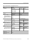
1
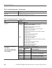
The trigger position errors are typically less than the values given here. These values are for triggering signals having a
slew rate at the trigger point of ≥ 0.5 division/ns.
2
The waveform interval (WI) is the time between the samples in the waveform record. Also, see the footnote for the
characteristics Sample Rate Range or Interpolated Waveform Rates in Table 2–4, on page 2–12.
3
The minimum sensitivity for obtaining a stable trigger. A stable trigger results in a uniform, regular display triggered on the
selected slope. The trigger point must not switch between opposite slopes on the waveform, and the display must not
“roll” across the screen on successive acquisitions. The TRIG’D LED stays constantly lighted when the SEC/DIV setting is
2 ms or faster but may flash when the SEC/DIV setting is 10 ms or slower.
4
The minimum signal levels required for stable logic or pulse triggering of an acquisition, or for stable counting of
a DC-coupled, events-delay signal. Also, see the footnote for Sensitivity, Edge-Type Trigger, DC Coupled in this table.
(Stable counting of events is counting that misses no events and produces no extra, phantom events).
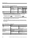
5
The minimum signal levels required for stable runt pulse triggering of an acquisition. Also, see the footnote for Sensitivity,
Edge-Type Trigger, DC Coupled in this table. (Stable counting of events is counting that misses no events).
6
The minimum signal levels required for stable pulse width or glitch triggering of an acquisition. Also, see the footnote for
Sensitivity, Edge-Type Trigger, DC Coupled in this table. (Stable counting of events is counting that misses no events).
7
For Logic, time between channels refers to the length of time a logic state derived from more than one channel must exist
to be recognized. For Events, the time is the minimum time between a main and delayed event that will be recognized if
more than one channel is used.
8
For Slew Rate Triggering, this is the minimum transition time, defined to be the time the user’s signal spends between the
two trigger threshold settings.
9
User Hold Time is the number selected by the user in the Hold Time Menu.