


Performance Verification Procedures
1–2
TDS 500D, TDS 600B & TDS 700D Performance Verification and Specifications
Input Channels vs. Model
When performing the procedures in this section, be aware that some TDS models
refer to input channels Ch 3 and Ch 4 as Aux 1 and Aux 2 respectively. Where
appropriate, both names will appear in the procedure, for example, Ch 3 (Aux 1).
The channel names for the various TDS models are shown below.
TDS Model Channel Names
TDS 540D, 580D, 644B, 684B, 754D, 784D, and 794D
Ch 1, Ch 2, Ch 3, and Ch 4
TDS 520D, 620B, 680B, and 724D Ch 1, Ch 2, Aux 1, and Aux 2
Conventions
Throughout these procedures the following conventions apply:
H Each test procedure uses the following general format:
Title of Test
Equipment Required
Prerequisites
Procedure
H Each procedure consists of as many steps, substeps, and subparts as required
to do the test. Steps, substeps, and subparts are sequenced as follows:
1. First Step
a. First Substep
H First Subpart
H Second Subpart
b. Second Substep
2. Second Step
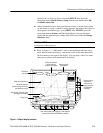
H In steps and substeps, the lead-in statement in italics instructs you what to
do, while the instructions that follow tell you how to do it, as in the example
step below, “Initialize the oscilloscope” by doing “Press save/recall SETUP.
Now, press the main-menu button...”.