


Brief Procedures
TDS 500D, TDS 600B & TDS 700D Performance Verification and Specifications
1–9
H Move the probe to the channel you selected.
b. Match the trigger source to the channel selected:
H Press TRIGGER MENU.
H Press the main-menu button Source.
H Press the side-menu button that corresponds to the channel selected,
Ch2, Ch3, or Ch4. (Some TDS models use Ax1 and Ax2 instead of
Ch3 and Ch4).
c. Set up the selected channel:
H Set the vertical SCALE to 200 mV.
H Set the horizontal SCALE to 200 ms. Press CLEAR MENU to
remove any menu that may be on the screen.
H Press SET LEVEL TO 50%.
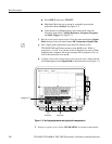
d. Verify that the channel is operational: Confirm that the following
statements are true.
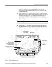
H The vertical scale readout for the channel under test shows a setting
of 200 mV, and a square-wave probe-compensation signal about
2.5 divisions in amplitude is on-screen. See Figure 1–1 on page 1–3
to locate the readout.
H The vertical POSITION knob moves the signal up and down the
screen when rotated.
H Turning the vertical SCALE knob counterclockwise decreases the
amplitude of the waveform on-screen, turning the knob clockwise
increases the amplitude, and returning the knob to 200 mV returns
the amplitude to about 2.5 divisions.
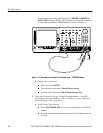
e. Verify that the channel acquires in all acquisition modes: Press SHIFT;
then press ACQUIRE MENU. Use the side menu to select, in turn, each
of the three hardware acquire modes and confirm that the following
statements are true. Refer to the icons at the left of each statement as you
confirm those statements.
H Sample mode displays an actively acquiring waveform on-screen.
(Note that there is noise present on the peaks of the square wave).
H Peak Detect mode displays an actively acquiring waveform
on-screen with the noise present in Sample mode “peak detected.”
H Hi Res mode (TDS 500D and 700D only) displays an actively
acquiring waveform on-screen with the noise that was present in
Sample mode reduced.