


Model 7600
Teledyne Analytical Instruments x
List of Figures
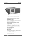
Figure 1-1: Model 7600A Infrared Gas Analyzer........................... 16
Figure 1-2: Model 7600 Description .............................................. 19
Figure 2-1: Slide Rail Mounting Dimensions ................................. 23
Figure 2-2: Input/Output Terminal Module..................................... 24
Figure 2-3: Mounting the I/O Module............................................. 24
Figure 2-4: Internal Piping with Single or Dual Measuring Units ... 26
Figure 2-5: External Piping with Single Inlet and Outlet ................ 27
Figure 2-6: External Piping with Two Pair of Inlet/Outlet (1).......... 28
Figure 2-7: External Piping with Two Pair of Inlet/Outlet (2).......... 28
Figure 2-8: Five Component Analysis System .............................. 31
Figure 2-9: Model 7600 Electrical Connections............................. 32
Figure 2-10: Noise Suppression.................................................... 33
Figure 2-11: I/O Cable Connection................................................ 33
Figure 3-1: Front Panel of the Model 7600.................................... 35
Figure 3-2: Interface Keys on the Front Panel............................... 35
Figure 3-3: Display Modes and Menu Hierarchy ........................... 37
Figure 3-4: Example Screen—5 Component Analysis 12
Channels................................................................................ 38
Figure 3-5: Setting/Selection Screen Areas .................................. 41
Figure 3-6: Hysteresis Example for a High Limit Alarm................. 57
Figure 3-7: Example Auto Calibration ........................................... 61
Figure 3-8: Example Auto Zero Calibration ................................... 67
Figure 3-9: Peak Alarm Example .................................................. 72
Figure 3-10: Output Hold for Manual Calibration........................... 75