


Infrared Gas Analyzer Maintenance
Teledyne Analytical Instruments 101
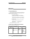
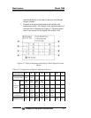
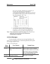
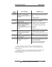
Where:
“Main” is signal input value from the main detector of each component.
“Comp” is signal input value from interference compensation detector of
each component. If low range exceeds the range of 0 to 10 vol %,
detector signal of “comp” is not usable.
In the above table, O
2
is excluded from the number of components.
Sensor values which are not included in measuring components
should be ignored.
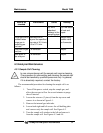
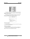
4.
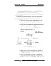
Adjust the primary side of the optical system (if
instrument is equipped with more than 1 measuring unit)
so that the onscreen values for (a) to (d) in 1-1 and 1-2 of
become as close to 0 as possible within ±100 range.
5.
Adjust on the secondary side of the optical system so that
the values for (e) to (h) in 2-1 and 2-2 become as close to
0 as possible within ±100 range.
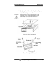
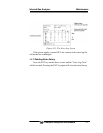
6.
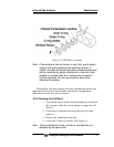
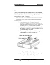
Operate the optical zero adjustment knob to change the
value displayed at (a) or (e). See Figure 4-8
Figure 4-8: Optical Zero Adjustment
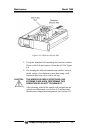
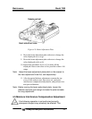
7. Move the beam adjustment plate sideways to change the
value displayed at (b) or (f ). See Figure 4-9.