


Infrared Gas Analyzer Installation
Teledyne Analytical Instruments 27
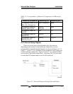
Table 2-1: Correspondence of Measured Components and Measuring
Units
Measuring components Measuring unit 1 Measuring unit 2
1-component meter for NO,
SO
2
, CO
2
, CO and CH
4
Each component None
2-component meter for
NO/SO
2
and CO
2
/
CO
NO/SO
2
CO
2
/
CO
None
2-component meter for
NO/CO
NO CO
3-component meter for
NO/SO
2
/CO
NO/SO
2
CO
4-component meter for
NO/SO
2
/CO
2
/CO
NO/SO
2
CO
2
/CO
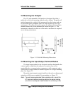
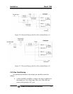
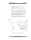
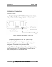
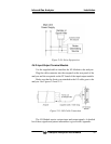
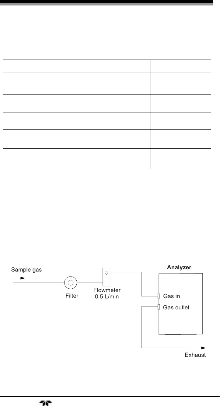
2.5.2 External Piping Diagram
There are several ways to bring sample gas to the analyzer
depending on the number of inlet/outlet gas connections on your
instrument Recommended piping diagrams are shown in Figures 2-5, 2-
6 and 2-7. Figure 2-5 is a schematic for an instrument with a single pair
of inlet/outlet gas connections. Figures 2-6 and 2-7 are used when there
are two pair of inlet/outlet connections. Note that a NO
2
/NO converter
is used when NO measurement is used for NOx analysis.
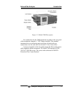
Figure 2-5: External Piping with Single Inlet and Outlet