


Maintenance Model 7600
Teledyne Analytical Instruments 100
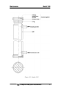
introduced directly to the inlet of analyzer unit through
the gas cylinder.
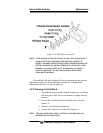
3.
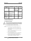
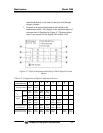
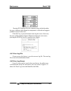
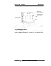
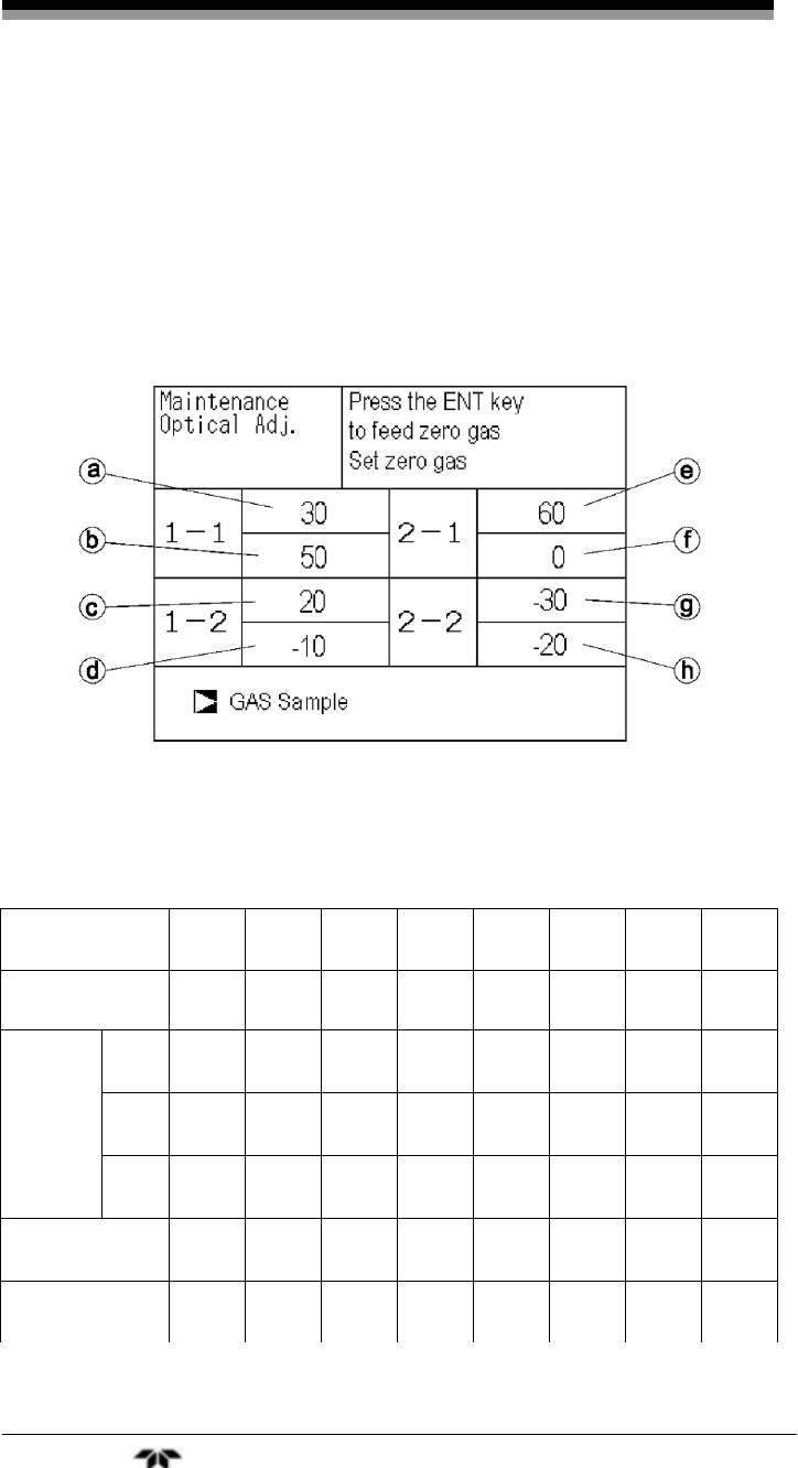
Proceed to an optical adjustment as described in the
maintenance mode. The display on the operation panel of
the main unit is illustrated in Figure 4-7. Balance adjust-
ment is not required if the display falls within ±100.
Figure 4-7: Optical Adjustment Display for Dual Optical System
Option
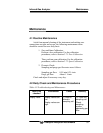
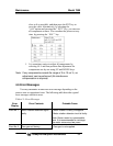
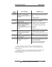
Table 4-2: Components of Optical Adjustment Screen
No. Of Components
to be measured
a b c d e f g h
1-component meter Main Comp – – – – – –
NO/SO2
NO
Main
NO
Comp
SO2
Main
SO2
Comp
– – – –
CO2/CO
CO2
Main
CO2
Comp
CO
Main
CO
Comp
–
2-
component
meter
NO/CO
NO
Main
NO
Comp
– –
CO
Main
CO
Comp
– –
3-component meter
NO/SO2/CO
NO
Main
NO
Comp
SO2
Main
SO2
Comp
CO
Main
CO
Comp
– –
4-component meter
NO/SO2/CO2/CO
NO
Main
NO
Comp
SO2
Main
SO2
Comp
CO2
Main
–
CO
Main
CO
Comp