


Infrared Gas Analyzer Installation
Teledyne Analytical Instruments 25
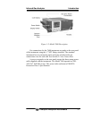
2.5 Gas Connections
Gas connections are made on the rear panel of the analyzer. Adhere
to the following guidelines when making gas connections:
• Use a corrosion resistant tube such as Teflon, stainless or
polyethylene to connect the instrument to a sampling system.
Even if there is a danger of corrosion, refrain from using
rubber or soft vinyl tubing. This would result in instrument
inaccuracies due to gas absorption by the piping materials.
• Pipe connection port is Rc1/4 female thread (or NPT1/4).
Piping should be cut as short as possible for quicker
response. About 4 mm inner diameter is recommended.
• Keep out dust and debris from the tubing and connections .
Always use clean tubing and fittings.
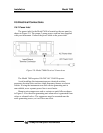
Connect the gas tube as follows:
• Sample gas inlet: Attach the sample gas tube to the inlet
fitting. The sample gas should be filtered and dehumidified
before passing into the analyzer. This port is also used to
connect the zero and span calibration gases.
• The gas flow should be constant within the range of 0.5
L/min ±0.2 L/min.
• Sample gas outlet: Sample gas exits the analyzer through
the gas out port at atmospheric pressure. Exhaust gases must
be vented safely.
• Purge gas inlet: This connection is used for purging the
inside of the analyzer. Purging is not always required. See
Section 2.5.6 Purging the Analyzer. When required, use dry
N
2
or instrumentation air for the purge gas. Use a flow rate of
1L/min or greater).
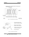
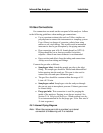
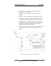
2.5.1 Internal Piping Diagram
Note: When the purge gas inlet is provided, an internal
connection to measuring unit 2 is installed.