


Maintenance Model 7600
Teledyne Analytical Instruments 102
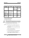
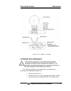
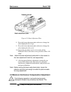
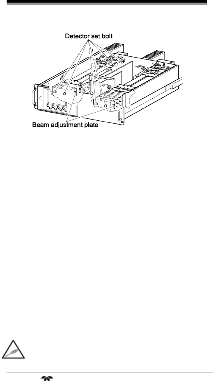
Figure 4-9: Beam Adjustment Plate
8. Move the beam adjustment plate sidewise to change the
value displayed at (c) or (g).
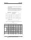
9.
Move the beam adjustment plate sidewise to change the
value displayed at (d) or (h).
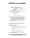
10.
Repeat the procedures in (6) to 9) to make all the
displayed values come close to 0 as possible within ±100
range.
Note: Adjust the beam adjustment plate which is the nearest to
the zero adjustment knob first, and sequentially.
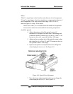
11. After the optical balance adjustment, remount the top
cover of the analyzer unit, then carry out a moisture
interference compensation adjustment, and perform zero
and span calibrations.
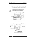
Note: Before moving the beam adjustment plate, loosen the
detector set bolts (just enough to make the plate movable
for snug adjustment.
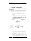
4.5 Moisture Interference Compensation Adjustment
If the following operation is not performed correctly,
subsequent analysis may adversely be affected. This