


Effective December, 1998
IL 33-DAH-1
Page 10
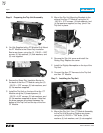
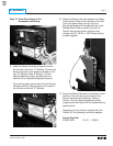
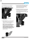
C. Route the CPT Harness between the Trip Unit
and the Insulation Barrier to the CPT. Strip .250"
of insulation and attach a .138" ring terminal to
each wire of the CPT Harness. Connect the
CPT Harness wires to the X1 and X2 terminals
of the CPT.
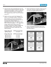
D. Position the fuses on the High Voltage (HV)
Wires in an accessible location. Route the HV
Wires between the Trip Unit and Insulation
Barrier to the Breaker Mounted CPT, then cut
the Load Side of each HV Wire to an
appropriate length. Strip .250" from the Load
Side HV Wires and attach a .138" ring terminal
to each. Attach the HV Wires to the CPT
terminals to achieve the required voltage (see
the following table). The HV Wires will be
connected to the Phase Frames later in the
Retrofit process.
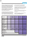
Voltage Required CPT Terminals Used
600 Volt Circuit H1 & H2
Voltage Required CPT Terminals Used
480 Volt Circuit H1 & H4
240 Volt Circuit H1 & H3
208 Volt Circuit H1 & H2
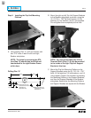
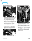
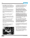
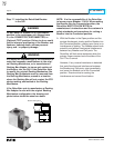
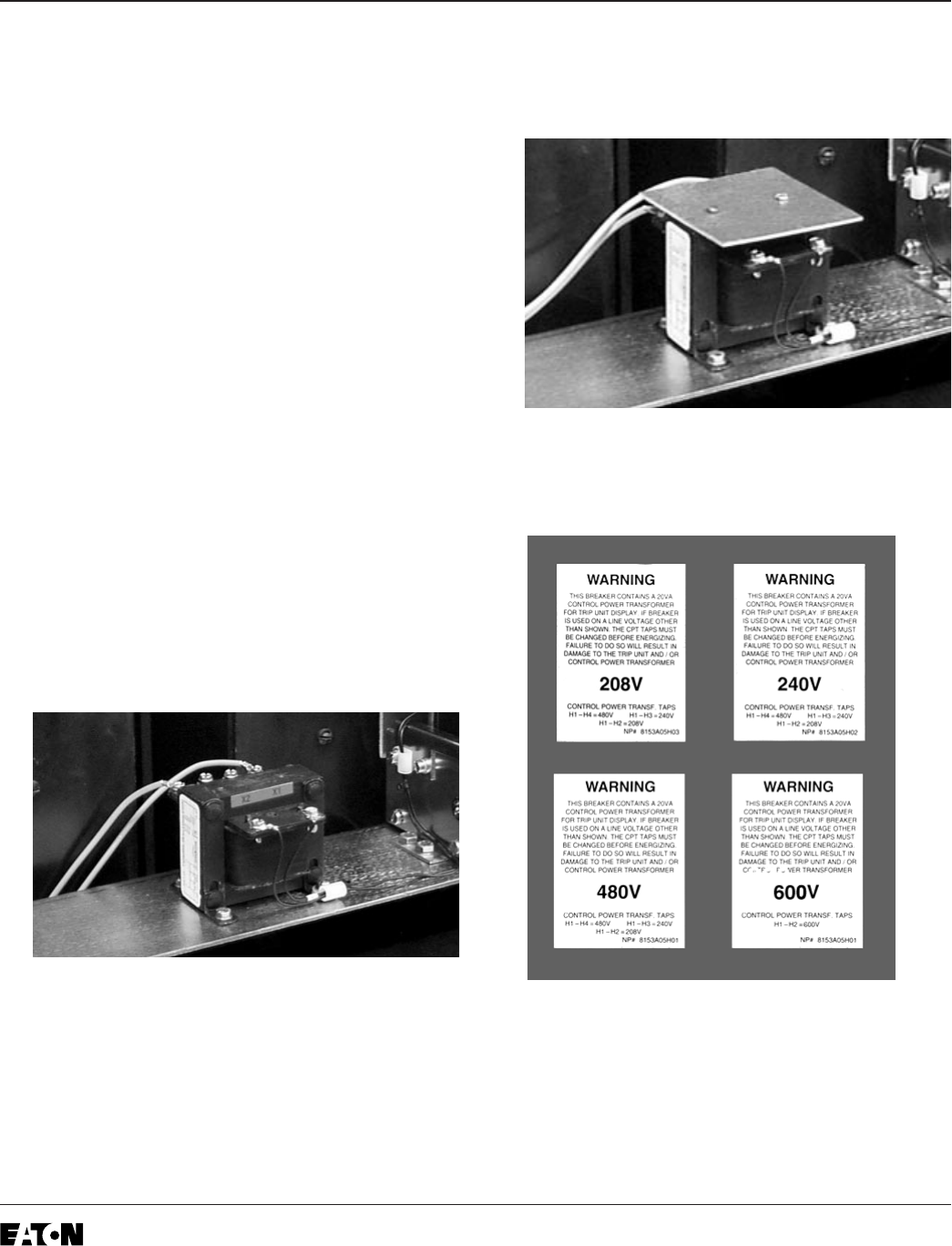
E. Attach the Glass Poly Insulation Plate to the top
of the CPT, as shown, using the screws and
lock washers supplied with the CPT kit.
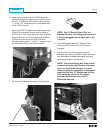
F. Attach the appropriate warning label for the
Breaker to the left of the CPT on the Trip Unit
Mounting Platform.