


Effective January, 1998
IL 33-DAH-1
Page 25
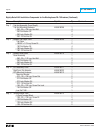
Symbols
2-Point Terminal Block 9
510 Basic Retrofit Kits 13
A
Auxiliary Switch 14
B
Breaker Mounted CPT 9
C
Cell Harness 15
CPT Terminals 10
D
Drilling Plan “A” 5
DTA Assembly 8
DTA Extension Harness 13
F
Final Connection of the Harnesses and Wiring 11
G
General Breaker Preparation 3
Glass Poly Insulation Plate 10
H
HV Wires 12
I
Installing the 2-Point Terminal Block 9
Installing the Auxiliary Switch 14
Installing the Breaker Mounted CPT 9
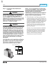
Installing the DTA Assembly 8
Installing the Reset Arm Assembly 7
Installing the Retrofitted Breaker in the Cell 16
Installing the Sensors 4
Installing the Trip Finger 7
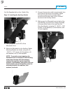
Installing the Trip Unit 6
Installing the Trip Unit Mounting Platform 5
K
Kit Components Table 1
M
Mounting the Cell Harness 15
P
Phase Convention 12
PT Wires 12
R
Racking Bar Adapter 16
Removing the Original Electromechanical Trip Units 3
Reset Arm Assembly 7
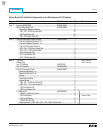
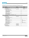
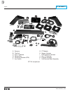
Retrofit Kit Installation Components 17
Retrofitted Breaker 16
S
SAFETY PRECAUTIONS 1
Sensor Style No. 11
Sensors 4
T
Testing the Breaker 15
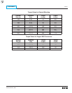
Torque Values for Copper BUS Connectors 21
Torque Values for General Mounting 21
Trip Finger 7
Trip Unit Assembly 6
Trip Unit Mounting Platform 5
INDEX