


Effective December, 1998
IL 33-DAH-1
Page 12
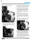
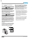
D.
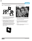
For Kits Supplied with a PT Module Only.
Refer to Section 7-3, Power Flow Convention of
the Retrofit Application Data, supplied with the
Retrofit Kit for additional wiring information and
to verify the Phase Convention used on this
Breaker Application.
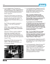
Route the PT Wires between the Glass Poly
Insulation Barrier and the back of the Trip Unit,
then down along the right Trip Unit Mounting
Bracket to the area where the original
Electromechanical Trip devices were removed
(Step 2).
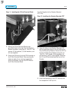
The PT Wires are marked for connection to
Phases 1, 2, and 3 with corresponding
numbers.
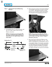
NOTE: Before cutting the PT Wires, verify
the Phase Convention used on the Breaker
Application.
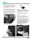
Route the PT Wires to a position suitable for
attachment to the proper Breaker Phase
Frames. Move the PT Wire markers to a
position where they will still be attached to the
wires after cutting. Cut the wires to length, strip
each wire .250", and install a .250" ring terminal
to each PT Wire.
Connect each PT Wire to the corresponding
Breaker Phase Frames using the (3)
.250-20 × .500" bolts, (3) lock washers, and
(3) flat washers supplied.
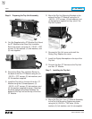
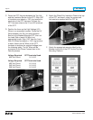
E.
For Kits Supplied with a Breaker Mounted CPT
Only.
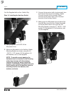
Route the
Line Side
HV Wires to the rear
of the Breaker through the opening in the
Breaker Back Plate and along the rear of the
Breaker to the top Phase Frames.
Note: The power convention of the
Westinghouse DA-75 Series Breakers is
normally
Top to Bottom
, meaning the Top
Breaker Phase Frames are on the
Line Side
of the Breaker and the Bottom Breaker
Stabs are on the
Load Side.
The HV Wires from the CPT MUST BE
ATTACHED to the
Line Side
of the Breaker. If
it is determined that the power flow for the
Breaker application is opposite the normal
convention, the HV Wires must be attached
to the Bottom Phase Frames. The bolts used
to secure the PT Wires can be used to
connect the HV Wires.
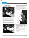
Note: The
Line Side
HV Wires are longer
than necessary and are cut during the
following steps. Before cutting the wires, be
sure that sufficient length is left so that the
connections can be made to the correct
Finger Clusters or Phase Frames.
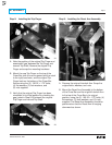
F.
For Kits Supplied with a Breaker Mounted CPT
Only.
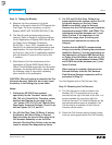
Using a .234" drill, drill and tap one hole in
the top of the Phase 1 and 2 or Phase 2 and 3
Phase Frames.
G.
For Kits Supplied with a Breaker Mounted CPT
Only.
Cut the HV Wires to the appropriate
length for attachment to the appropriate Phase
Frames. Strip .250" from each HV Wire and
attach a .250" ring terminal. Using the (2)
.250-20 × .500" bolts, (2) flat washers, and (2)
lock washers supplied, connect the HV Wires
to the appropriate Phase Frames.