


Effective December, 1998
IL 33-DAH-1
Page 6
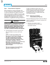
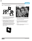
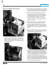
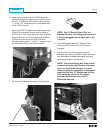
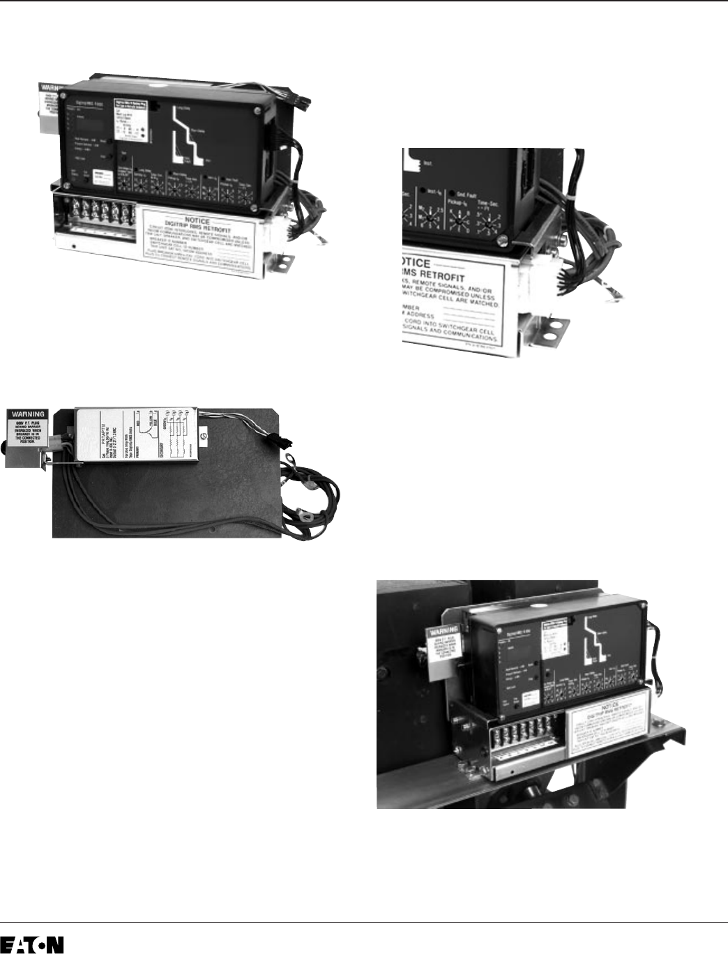
Step 6: Preparing the Trip Unit Assembly
A.
For Kits Supplied with a PT Module Only.
Mount
the PT Module to the Glass Poly Insulation
Barrier as shown, using the (2) .138-32 × .500"
screws, (4) flat washers, (2) lock washers, and
(2) nuts supplied.
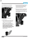
B. Secure the Glass Poly Insulation Barrier to
the back of the Aux. CT Module using the (2)
.190-32 × .375" screws, (2) lock washers, and
(2) flat washers supplied.
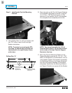
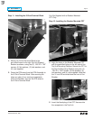
C. Install the Trip Unit on the top of the Aux. CT
Module using the (2) brass spacers, (2)
.190-32 × 4.00" screws, (2) lock washers, and
(2) flat washers supplied as shown. Note that
the brass spacers are placed between the
bottom of the Trip Unit and the top of the Aux.
CT Module.
D. Mount the Trip Unit Mounting Brackets to the
sides of the Aux. CT Module, using the (4)
.190-32 × .375" screws, (4) lock washers, and
(4) flat washers supplied, so they “pinch” the
Trip Unit in place.
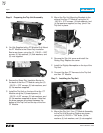
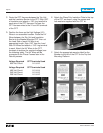
E. Remove the Trip Unit cover and install the
Rating Plug. Replace the cover.
F. Install the Digitrip Nameplate on the top of the
Trip Unit.
G. Connect the Aux. CT Harness to the Trip Unit
and Aux. CT Module.
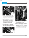
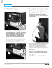
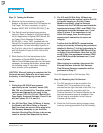
Step 7: Installing the Trip Unit
A. Mount the Trip Unit / Aux. CT Module Assembly
to the Trip Unit Mounting Platform as shown,
using the (4) .250-20 × .750" bolts, (8) flat
washers, (4) lock washers, and (4) nuts supplied.