


Effective December, 1998
IL 33-DAH-1
Page 13
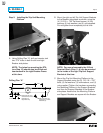
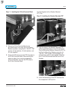
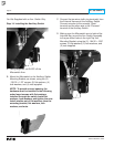
H. Feed the two wires from the DTA Extension
Harness through the opening in the left side of
the Aux. CT Module. Connect the wire marked
“+” to the “OP” terminal and the unmarked wire
to the “ON” terminal.
I. Route the DTA Extension Harness between the
Glass Poly Insulation Barrier and the back of
the Trip Unit, then down along the right Trip Unit
Support Bracket to the 2-Point Terminal Block.
Connect the wire from the DTA Extension
Harness marked with “+” to the “+” terminal and
the unmarked wire to the other terminal.
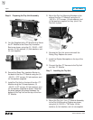
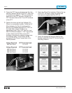
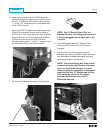
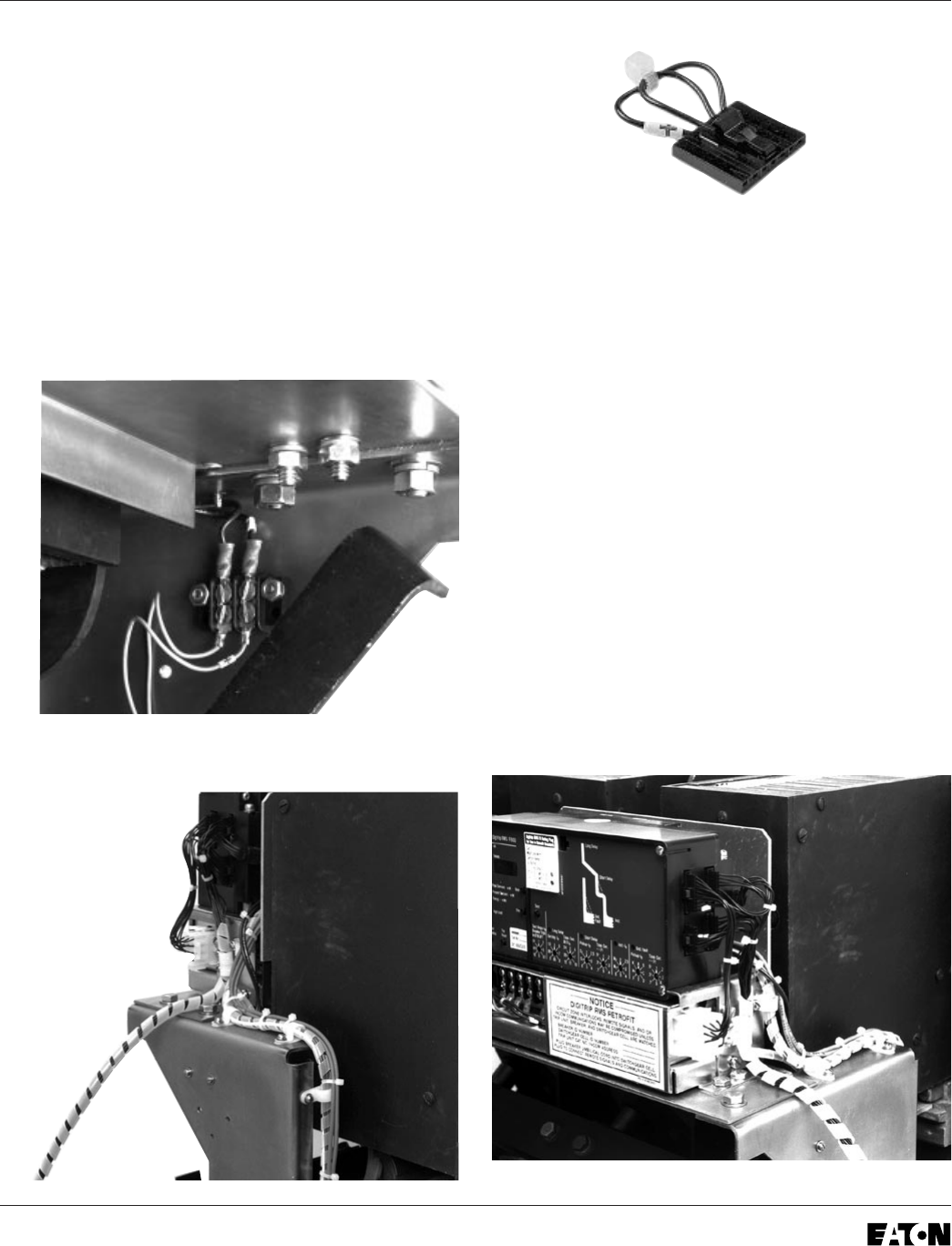
J. Connect the External Harness to the Trip Unit.
NOTE: For 510 Basic Retrofit Kits, the
External Harness is the plug pictured above.
It is to be plugged into the right side of the
Trip Unit.
K.
For Kits Supplied with a PT Module Only.
Connect the PT Harness to the External
Harness.
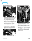
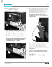
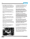
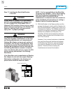
L. Use the wire ties, wire clamps, and self
adhesive wire clips provided to dress all wires
and harnesses to keep them away from any
moving parts within the Breaker.
NOTE: The self adhesive wire clips should
be attached to the right Breaker side panel
to secure the Sensor Harness. The wire
clamps should be attached to the hardware
mounting the Aux. CT Module and the Trip
Unit, as shown, to secure the Sensor
Harness, External Harness, and PT
Extension Harness.